GE Monogram® Installation Instructions with Optional Trim Kit Installation Instructions CleanSensor Dishwashers Models ZBD3500 BB ZBD3500 WW
Before you begin—Read these instructions completely and carefully. IMPORTANT: Save these instructions for local inspector’s use. IMPORTANT: OBSERVE ALL GOVERNING CODES AND ORDINANCES. NOTE TO INSTALLER: Be sure to leave these instructions with the Consumer. NOTE TO CONSUMER: Keep these instructions with your Use and Care Book for future reference. CAUTION WARNING This appliance must be properly grounded. See “Power Supply”, page 9.
Design Information CleanSensor Dishwashers Models Available ZBD3500 WW White CleanSensor dishwasher ZBD3500 BB Black CleanSensor dishwasher Designed for versatility, the Monogram builtin dishwasher adapts easily to virtually any installation. Dimensions & Clearances (Both Models) A – 34" min. adjustable to 35" max.
Design Information CleanSensor Dishwashers Advance Preplanning Information • These Monogram dishwashers are supplied as either a white or black model. Door and access panels may be covered with custom decorative panels of wood or other materials to match cabinetry or other appliances. See “Optional Trim Kits,” page 5. • A custom toekick can be installed over the supplied toekick to match cabinet material when cabinet depth is 25" or more.
Design Information CleanSensor Dishwashers Side-by-side Installation • Two Monogram dishwashers may be installed side-by-side for greater capacity. Optional Panel and Custom Panel Kits Custom Panel Kits • GPF425 Trim Kit – Provides for the installation of 1/4" thick custom door and access panels. • GPF475 Trim Kit – Provides for the installation of 3/4" thick custom door and access panels. This kit includes GPF100 heavy springs kit for panels that weigh over 4 pounds.
Installation Preparation CleanSensor Dishwasher Parts Supplied ■ Two Phillips head countertop mounting screws taped to dishwasher.
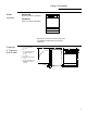
Installation Preparation CleanSensor Dishwasher Single Dishwasher • The rough cabinet opening must be 24" min. deep and 24" wide. The opening height should be 34" min. and 35" max. • The opening should be free of extraneous pipes and wires. 34-1/2"±1/4" Underside of Countertop to Floor This Wall Area must be Free of Pipes or wires 5" 4" 24" Min. 5" 4" Plumbing and Electric Services Must Enter Inside This Area 6" Cabinets Square and Plumb 24" Min.
Installation Preparation CleanSensor Dishwasher Water Supply 1-1/2" Dia. Hole Shut-off Valve 4" 5" 4" 5" Hot 2" from Cabinet Cabinet Face • Hot water line may enter from either side, from the rear, or from the floor within the shaded area shown. • Cut a hole approximately 1-1/2" in diameter to admit water line. • Install a hand shut-off valve in the supply line in an accessible location, such as under the sink. (The shut-off valve is optional, but recommended and may be required by local codes.
Installation Preparation CleanSensor Dishwasher Power Supply WARNING FOR PERSONAL SAFETY: REMOVE HOUSE FUSE OR OPEN CIRCUIT BREAKER BEFORE BEGINNING INSTALLATION. DO NOT USE AN EXTENSION CORD OR ADAPTER PLUG WITH THIS APPLIANCE. FOLLOW NATIONAL ELECTRICAL CODES OR PREVAILING LOCAL CODES AND ORDINANCES.
Installation Preparation CleanSensor Dishwasher Prepare Drain Plumbing • Follow local codes and ordinances. • Dishwasher drain hose must not exceed 10 feet in length for proper drainage. –The dishwasher is supplied with a 1/2" I.D. drain hose, 78" long. Add up to 42" length to the factory supplied hose if necessary. • Dishwasher must be connected to waste line with an air gap (not supplied) or 32" minimum, high drain loop (depending on local codes and ordinances) to prevent back flow into the dishwasher.
Installation CleanSensor Dishwasher Step 1 Check Door Balance CAUTION Do not remove wood base until you are ready to install the dishwasher. The dishwasher will tip over when the door is opened. • Unlatch door and remove all foam and cardboard packaging. • Check balance by opening and closing door. If necessary, close latch and adjust one or both springs before the wood base is removed. Note: Spring hook must be turned to the outside. Move spring hook back to increase tension.
Installation CleanSensor Dishwasher • Remove the two screws below the access panel and set aside. • Loosen the two screws located between the door and access panel. Do not attempt to remove these screws. They are secured to the access panel with washers. es s Pa ne l Back Out 2 Screws To ek ick Ac c Step 4 Remove Access Panel And Toekick Remove 2 Screws Step 5 Install Power Cord (If Used) Skip this step If dishwasher will be wired direct.
Installation CleanSensor Dishwasher Step 7 Position Water Line And Power Supply • Position the water supply line and wiring on the floor of the opening to avoid interference with base and components under dishwasher. Water Line Step 8 Insert Drain Hose Step 9 Install Optional Trim Kits And Tub Flange Trim Kit. • Stand the dishwasher upright and move to the front of the opening. • Insert drain hose into the hole previously drilled in the cabinet wall.
Installation CleanSensor Dishwasher Step 10 Slide Dishwasher Into Cabinet Step 11 Level Dishwasher, Align Connections Step 12 Position dishwasher and fasten to cabinet CAUTION DO NOT PUSH AGAINST FRONT DOOR PANEL WITH KNEES. Damage to the door panel will occur. • Level the dishwasher by adjusting the four leveling legs individually for correct alignment. • Dishwasher should be level, left to right and front to back for best performance.
Installation CleanSensor Dishwasher Step 14 Connect Drain Line Follow all local codes and ordinances. • The molded end of the drain line is designed to fit 5/8", 3/4" and 1" diameter connections to air gap, waste tee or disposer. • Cut on marked line as required for your installation.
Installation CleanSensor Dishwasher Step 16 Installation Check List ■ Check to be sure power is OFF. ■ Open dishwasher door and remove all foam and cardboard packaging. ■ Remove literature package with Use & Care manual. ■ Read the Use & Care manual to familiarize yourself with the operation of the dishwasher. ■ Add two quarts of water to the bottom of the dishwasher to lubricate the pump seal. ■ Remove the protective film, if present, from the control panel, door and access panels.
GPF100 Trim Kit Heavy Door Springs Tools and Materials required: • 1/4" socket driver • Phillips screwdriver • Gloves to protect against sharp edges For installation of a custom dishwasher door panel weighing 4 pounds to 8 pounds. WARNING To prevent electric shock, disconnect electrical power supply to dishwasher before changing panels. Do not operate dishwasher while changing panels or when lower access panel assembly is removed. Step 1 • Turn off water supply. • Latch dishwasher door.
GPF400/600/700 Series Trim Kits Door and Access Panel Kits GPF400B, Black door and access panels GPF400W, White door and access panels GPF600B, Black door panel GPF600W, White door panel GPF700B, Black access panel GPF700W, White access panel Tools and Materials required: • 1/4" socket driver • Phillips screwdriver • Safety Glasses • Gloves to protect against sharp edges WARNING To prevent electric shock, disconnect electrical power supply to dishwasher before changing panels.
GPF400/600/700 Series Trim Kits Door and Access Panel Change Step 2: Install New Door Panel Cover New Door Pane l Cover Note: The new door panel cover will completely cover the existing door. Do not remove the original door panel. For GPF400 and GPF600 Kits: • Remove protective plastic film. • Tip door panel and slide up and under bottom and sides of escutcheon. • Snap door panel over the door and slide upwards, under the escutcheon.
GPF400S Trim Kit Stainless Steel Door and Access Panels Tools and Materials required: • 1/4" socket driver • Phillips screwdriver • Electric drill • 1/8" drill bit • Safety glasses • Center punch • Gloves to protect against sharp edges The GPF400S Stainless steel trim kit covers the existing door and access panel. This kit includes: • Door and access panel covers. • 12 screws.
GPF400S Trim Kit Stainless Steel Door and Access Panels Step 2: Install Stainless Door Panel Cover New Door Pane l Cover • Remove protective plastic film. • Tip door panel and slide up and under bottom and sides of escutcheon. • Snap door panel over the door and slide upwards, under the escutcheon. Step 3: Install GPF100 Spring Kit This kit must be installed to achieve proper door balance which is affected by the addition of this stainless door panel.
GPF425 Series Trim Kit 1/4" Custom Panels GPF425B, Black Trim Kit GPF425W, White Trim Kit GPF425A, Almond Trim Kit Tools and Materials required: • 1/4" socket driver • Phillips screwdriver • Electric drill • 1/8" drill bit • Masking tape • Safety glasses • Gloves to protect against sharp edges Step 1: Cut 1/4" Thick Custom Panel To Size The GPF425 trim kits provide for the installation of 1/4" thick custom door and access panels.
GPF425 Series Trim Kit 1/4" Custom Panels Step 3: Install Door Panel Trim And Custom Panel Remove the protective plastic covering from side trim pieces. “Z” Trim A. Place bottom trim against the bottom of the door panel and drive center screw, then left and right screws. B. Slide “Z” shaped trim under the escutcheon. C. Slide custom door panel under the “Z” trim and bottom trim. D. The notch on the side trim pieces go towards the front.
GPF425 Series Trim Kit 1/4" Custom Panels Step 4: Install Custom Access Panel • Place bottom trim against the bottom of the access panel. • Install color matched screw in the center, then left and right screws. • Gently, bend both ends of the bottom trim upwards to form a “U” shape. • Slide the 1/4" custom panel down into “U” shaped trim. • Place top trim over the panel. Use masking tape to hold in place. • Drill 3 holes into the top of the trim and into the assembly.
GPF475 Series Trim Kit 3/4" Custom Panels Tools and Materials required: • 1/4" socket driver • Phillips screwdriver • Electric drill • 1/8" and 3/16" drill bits • Carpenters square • Safety Glasses The GPF475 Trim Kit provides for the installation of 3/4" thick custom door and access panels with a typical 4" high toekick. This Kit includes: • Door panel support • 5, 5/8" phillips flat head screws • 3 round head screws • GPF100 spring kit.
GPF475 Trim Kit 3/4" Custom Panels Step 2: Remove Lower Access Panel Assembly • Remove the two screws below the access panel. Retain screws. • Loosen the two screws located between the door and the access panel. Do not attempt to remove these screws. They are secured to the access panel with washers. • Remove the access panel assembly and toekick from the dishwasher. Set aside. Escutcheon Door Panel NOTE: Do not remove the insulation behind the access panel or toekick.
GPF475 Trim Kit 3/4" Custom Panels Step 3 (continued) Remove Tape Covering Adhesive Strips Screw Holes for Vertical (Typical) Wood Grain Screw Holes for Horizontal Wood Grain Direction C. Remove the custom panel from the support. • Remove tape from adhesive strips on the metal support – on the side that touches the custom panel. • Carefully, position the metal support onto the custom panel with center line showing through the triangle. Press the metal support against the panel. D.
GPF475 Trim Kit 3/4" Custom Panels Step 5 Install Custom Panel To Access Assembly • Drill 3 holes 3/16" dia. into the access panel as shown. • Place the custom panel onto the access assembly and mark hole locations. • Drill 3 holes, 1/8" dia. holes, 5/8" deep into the custom panel. • Align the custom panel with screw holes and drive 3 screws into the back side of the assembly panel and through the custom panel. The top edges should align evenly. 1/2" to 2" 1/2" to 2" 1/2" to 2" 3/16" Dia.
GPF53 Mounting Kit Mounting Brackets Tools and materials required: • 5/16" nut driver • Phillips screwdriver • Safety glasses Position Mounting Brackets • Fold factory installed flanges back 180° and flatten against tub frame. • Position mounting brackets over frame and in recessed area, as shown. Secure Mounting Brackets • Measure width of cabinet opening. • Insert two 10/32" machine screws into each bracket. Do not tighten. • Adjust brackets to match the cabinet opening width.
Notes 30
Notes 31
NOTE: While performing installations described in this book, safety glasses or goggles should be worn. To obtain specific information concerning any Monogram product or service, call GE Answer Center® consumer information service at 800.626.2000—any time, day or night. For Monogram local service in your area, call 1-800-444-1845. ® Monogram. General Electric Company Louisville, KY 40225 NOTE: Product improvement is a continuing endeavor at General Electric.