
Specification Guide

For questions about your
appliance, please call 1-800-626-2000.
Product Specication Created 10/19PAGE 3 OF 5
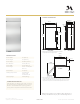
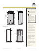
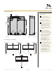
STANDARD INSTALLATION
HELPFUL TIPS
24" (61.0)
2 3/8"
(6)
4 1/2"
(11.4)
7/16"
(1.1)
Trim overlap
35 1/2" (90.2)
2 5/16"
(5.9)
*83 1/2" min
*84 1/2
" max
(212.1-214.6)
*Trim will overlap
additional 7/16"
3 1/2"
(8.9)
75
1/2
"
(191.8)
From floor
to bottom
of electrical
area
3 1/2"
(8.9)
SIDE VIEWFRONT VIEW
W
ELEC.
5 1/2"
(14.0)
9"
(22.9)
SIDE VIEW INSTALLED
WITH ANTI-TIP BRACKET
81 1/2"
(207.0)
ZIRS360NXLH
5"
(12.7)
5"
(12.7)
WATER
3 1/2"
(9.0)
Use two
additional hole
locations at end
of brackets
Wall
Studs
Bracket
mounted
into vertical
wall studs
C
Ensure holes
selected are
centered on
the studs
L
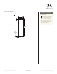
FRONT VIEW OF CUTOUT
WITH ANTI-TIP BRACKET
A
Mounting the junction box in this
location will also allow for front
accessibility through access panel.
B
Water supply area.
WARNING:
e refrigerator is top heavy and
must be secured to prevent the
possibility of tipping forward.
Failure to do so may result in
death or serious injury.
e information below is for
cabinet design only. When
installing the anti-tip system you
must use the product installation
instructions.
e information below applies to all
installation constructions:
• A wall bracket, bolts and toggles will
be supplied with the unit.
• e bolts will be used to attach
bracket to wall in 4 locations. Two
of the locations must penetrate the
center of the wall studs.
• e toggles are used for stability in
drywall and when metal studs are
encountered. Lag bolts are used in
wood studs.
• In installation opening, measure 81"
from floor and draw a horizontal line.
• Locate and mark the wall studs on
horizontal line. Verify at least two
studs have their centerlines within
the center 32 1/2" of installation
opening to ensure 2 wall studs
are penetrated.
• e bracket will be centered left
to right in opening with bottom of
bracket on the horizontal line.
• When unit is placed in opening, the
bracket tabs will align with openings
in back of the unit. e unit will be
secured to the bracket using supplied
“L” bolts.
See Installation Instructions for
detailed instructions.
24" (61.0)
2 3/8"
(6)
4 1/2"
(11.4)
7/16"
(1.1)
Trim overlap
35 1/2" (90.2)
2 5/16"
(5.9)
*83 1/2" min
*84 1/2" max
(212.1-214.6)
*Trim will overlap
additional 7/16"
3 1/2"
(8.9)
75
1/2
"
(191.8)
From floor
to bottom
of electrical
area
3 1/2"
(8.9)
SIDE VIEWFRONT VIEW
W
ELEC.
5 1/2"
(14.0)
9"
(22.9)
SIDE VIEW INSTALLED
WITH ANTI-TIP BRACKET
81 1/2"
(207.0)
ZIRS360NXLH
5"
(12.7)
5"
(12.7)
WATER
3 1/2"
(9.0)
Use two
additional hole
locations at end
of brackets
Wall
Studs
Bracket
mounted
into vertical
wall studs
C
Ensure holes
selected are
centered on
the studs
L
FRONT VIEW OF CUTOUT
WITH ANTI-TIP BRACKET
A
B
STANDARD INSTALLATION
ANTI-TIP BRACKET