Installation Instructions If you have questions, call 800.GE.CARES or visit our website at: www.monogram.
Installation Instructions BEFORE YOU BEGIN WARNING: Read these instructions completely and carefully. TO REDUCE THE RISK OF FIRE, ELECTRICAL SHOCK OR INJURY TO PERSONS, OBSERVE THE FOLLOWING: A. Use this unit only in the manner intended by the manufacturer. If you have any questions, contact the manufacturer. B. Before servicing or cleaning unit, switch power off at the service panel and lock service panel to prevent power from being switched on accidentally.
Installation Instructions CONTENTS Step 1, Determine Ductwork and Wiring Locations .... 10 Step 2A, Install Hood Onto Wall ................................... 11 Step 2B, Install Hood Beneath Soffit ............................ 12 Step 3, Connect Ductwork ............................................. 13 Step 4, Connect Electrical .............................................. 13 Step 5, Install Duct Covers ............................................. 13 Step 6, Install Motor ..............................
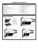
Advance Planning INSTALLATION CLEARANCES OPTIONAL DUCT COVER ACCESSORIES These vent hoods are designed to be installed onto a wall or beneath a soffit or cabinet. Installation with Warming Shelf • Hoods must be installed 32" Min., 38" Max over any type cooking surface when warming shelf is used. Installation without Warming Shelf • Install these hoods 30" Min. to 36" Max. above the cooking surface when installed over any professional style cooktop or range. • These hoods may be installed 24" min.
Advance Planning DETERMINE INSTALLATION HEIGHT, DUCT COVER ACCESSORIES These vent hoods must be installed 30" min. to 36" max. above the standard 36" high cooking surface. When installed with the warming shelf, allow 32" min. to 38" max. clearance. The exact hood installation height is determined by the ceiling height. 1. Measure the exact ceiling height. 2. Review the chart at right to determine the range of possible hood installation heights that can be accomplished with one or more duct covers. 3.
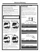
Advance Planning ADVANCE PLANNING POWER SUPPLY Ductwork Planning • These vent hoods are equipped for 10" round ductwork. For best performance, use 10" round ductwork on the 48" wide hoods. 30" and 36" hoods may be transitioned to 8" round. • This hood may be vented vertically through upper cabinets, soffit or ceiling. A duct transition piece is supplied for vertical exhaust. Use locally supplied elbows to vent horizontally through the rear wall. • Determine the exact location of the vent hood.
Advance Planning DUCT FITTINGS Use this chart to compute maximum permissable lengths for duct runs to outdoors. For best results, use 10" diameter duct. Note: Do not exceed maximum permissable equivalent lengths! Equivalent Length* Duct Piece 10" round to 8" round 5 ft. Round, straight 1 ft. (per foot length) 90° elbow 8" Dia. 52 ft. 10" Dia. 24 ft. 45° elbow 8" Dia. 31 ft. 10" Dia. 14 ft. Round wall cap with damper 8" Dia. 99 ft. 10" Dia. 41 ft. Round roof cap 8" Dia. 136 ft. 10" Dia. 56 ft.
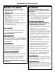
Installation Preparation TOOLS AND MATERIALS REQUIRED (NOT SUPPLIED) 1/4" pivoting hex socket Duct tape Hammer Key Hole Saw Wire cutter/stripper Pencil and tape measure Safety glasses Wire nuts Spirit level Flashlight Pliers Electric or battery operated drill and 1/8", 3/8" bits 10" round metal duct, length to suit installation. Phillips and flat blade screwdrdivers Strain relief for junction cover. Step ladder Metal Snips 120V 60Hz. 15 or 20 Amp, 2-wire with ground.
Installation Preparation PARTS PROVIDED Locate the parts packed with the hood. Duct Transition with Damper Wood Support with Original Screws 2 Stainless Steel Grease Filters (3 filters with 48" models) Heat Lamp (2 with 48" models) 2 Implement Rods and 4 Stand-offs Allen Wrench For Implement Rods Backguard Grease Tray Warming Shelf HARDWARE PACKAGE Locate and check contents. Screws shown actual size. Note: Hardware appearance may vary slightly.
Installation Instructions STEP 1 DETERMINE HOOD, DUCTWORK AND WIRING LOCATIONS • Use a level to draw the cooktop centerline location. Draw the line to ceiling height. • Measure desired distance from the bottom of the hood to the cooking surface. 9-7/8" Top of Hood Note: If you are installing the hood with duct covers, be sure to read “Using Duct Cover Accessories” page 7. Exact installation height may be determined by use of one or more duct covers.
Installation Instructions STEP 2A INSTALL HOOD ONTO WALL IMPORTANT: Framing must be capable of supporting up to 150 lbs. Install Transition Onto Top of Hood SKIP THIS STEP IF INSTALLING BENEATH A SOFFIT OR CABINET, GO TO STEP 2B. Duct Transition • Locate at least 2 vertical studs at the wood support. • Center the supplied wood support, left to right and below the 20" marked line. IMPORTANT: Remove shipping tape from damper and check that damper moves freely.
Installation Instructions STEP 2B Alternate Mounting Method INSTALL HOOD TO SOFFIT OR BENEATH CABINETS SKIP THIS STEP IF USING WALL MOUNTING METHOD When necessary, the hood may be installed so that it is supported by the soffit. • The soffit should be constructed with 2 x 4’s. • Determine the installation location on the wall. • Continue the centerline forward on the bottom of the cabinet or soffit.
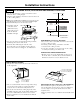
Installation Instructions STEP 3 CONNECT DUCTWORK STEP 5 INSTALL DUCT COVERS • Install ductwork, making connections in direction of airflow as illustrated. • Secure joints in ductwork with sheetmetal screws. • Wrap all duct joints with duct tape for an airtight seal. • Use duct tape to seal the flange connection. Air Flow Reach inside the Duct Tape hood and push Over Seam Screw the damper up and Screw to be sure it moves freely. Note: For easier handling, remove cardboard insert after film is peeled off.
Installation Instructions STEP 7 INSTALL FILTERS • Insert the filter into the opening and drop into the bottom. Raise filter to the top and lock into place. • Drop grease tray into the hood. The rear tabs should engage the slots in the hood track. • To remove the filters, grasp the latch, pull the filter up and lift out. STEP 8 INSTALL BACKGUARD AND SHELF INSTALL BACKGUARD: • Remove packaging. • Place backguard against the bottom of the hood to use as a template.
Installation Instructions STEP 9 INSTALL SHELF “ONLY” STEP 10 INSTALL IMPLEMENT RODS • Remove shelf packaging and protective film. • If installing the shelf alone, without the backguard, place shelf against the bottom of the hood and mark screw hole locations “B” on the wall. • Drill two 1/8" pilot holes. • If drill did not enter studs, enlarge holes to 3/8". • Insert wall anchors into enlarged holes. Remove screws from wall anchors.
Note: While performing installations described in this book, safety glasses or goggles should be worn. For Monogram® local service in your area, call 1.800.444.1845. Note: Product improvement is a continuing endeavor at General Electric. Therefore, materials, appearance and specifications are subject to change without notice. GE Consumer & Industrial GE Appliances General Electric Company Louisville, KY 40225 Pub. No. 49-80152-4 11-07 JR Printed in Italy ge.