GE Consumer & Industrial TECHNICAL SERVICE GUIDE Monogram 18-In.
IMPORTANT SAFETY NOTICE The information in this service guide is intended for use by individuals possessing adequate backgrounds of electrical, electronic, and mechanical experience. Any attempt to repair a major appliance may result in personal injury and property damage. The manufacturer or seller cannot be responsible for the interpretation of this information, nor can it assume any liability in connection with its use. WARNING To avoid personal injury, disconnect power before servicing this product.
TABLE OF CONTENTS Bottom Door Seal ................................................................................................. 19 Component Locator Views ..................................................................................... 7 Control Panel Features .......................................................................................... 6 Detergent/Rinse Module ....................................................................................... 15 Dishwasher Components ...........
Introduction The new Monogram 18" Built-In Compact Dishwasher has a size that allows the unit to fit in areas as small as 18 inches (45.72 cm) wide, 22 inches (55.88 cm) long, and 34 inches (86.36 cm) high. It is compact in size, yet delivers the performance of larger units. With a low power usage, this product model meets ENERGY STAR® guidelines for energy efficiency.
Nomenclature Model Number Z B D 1 8 0 0 K 0 0 S S Brand Z = Monogram Exterior Color BB = Black CC = Bisque SS = Stainless Steel WW = White Product Type BD = Built-In Dishwasher Engineering Model Suffix Model Designator Compact 18-in. Model Year Designator Nomenclature Serial Number The first two characters of the serial number identify the month and year of manufacture. Example: AG123456S = January, 2001 The serial plate of your dishwasher is located on the tub wall, just outside the door.
Control Panel Features Static Vent Door Latch Switch Control Timer Control Timer: START Close the dishwasher door and turn the control timer knob to the desired setting. Water fill begins and approximately 30 seconds later, the wash action begins. HEAVY WASH This cycle is for heavily soiled dishes and glassware. NORMAL WASH This cycle is for medium-soiled dishes and glassware. LIGHT WASH This cycle is for everyday dishes and glassware.
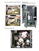
Component Locator Views Front View Insulation Control Panel Side Panel Access Panel Control Panel View Static Vent Door Latch Switch –7– Control Timer
Interior View (With Racks) Top Rack Bottom Rack Detergent/Rinse Module Static Dry Vent Detergent/Rinse Module Compartment View Detergent Compartment Sight Glass Rinse Agent Cap Compartment Lid –8–
Interior View of Basin (With Racks Removed) Right Side View (Side Panel and Insulation Removed) Spray Arm Door Tension Spring Fill Funnel Heating Element Pressure Switch Hose Fill Hose Filter Assembly Clamp Nut Microfilter Bottom View (Looking Up) Sump Drain Pump Motor Pump Assembly Capacitor –9–
Dishwasher Components Throughout this manual, features and appearance may vary from your model. Timer WARNING: Always turn off the electric power supply before servicing any electrical component, making ohmmeter checks, or replacing any parts. Note: All voltage checks should be made with a voltmeter having a full-scale range of 130 volts or higher. After service is completed, be sure all safety grounding circuits are complete, all electrical connections are secure, and all access panels are in place.
8. Release the door latch and allow the control panel cover to hang against the dishwasher door. Note: When installing the timer, it is important to align the threaded holes (A) and (B), marked in steps 3 and 4, with holes (A) and (B) in the control panel Threaded Hole (A) Timer Threaded Hole (B) Control Panel Align the threaded holes marked in steps 3 and 4 with the holes in the control panel. 9. Disconnect the ground wire from the timer. 10. Disconnect the connectors.
Door Switch and Latch Assembly The door switch and latch assembly is located on the door assembly behind the control panel cover. The dishwasher will not operate until the door is closed, the latch engages the door catch (holding the door firmly against the seal), and the normally open contacts of the double-pole, single-throw door safety switch are closed. 7. Remove the 4 screws that connect the door switch mounting bracket to the control panel cover. 8.
6. Inspect the gasket on the channel assembly. If the gasket shows obvious signs of wear or damage, replace the channel assembly. Static Dry System The static dry system operates through a vent located in the control panel. The vent allows hot air to exit the dishwasher tub and gradually remove moisture. Removal 1. Open the dishwasher door. Gasket 2. Remove the 6 screws that connect the control panel cover to the dishwasher door. (See Timer, step 6.) 3.
Door Panel Note: Make sure the edge of the control panel cover is flush with the edge of the door. 3. Align the screw holes on the control panel with the screw holes on the dishwasher door. The door panel covers the door to the dishwasher and protects the detergent/rinse module electronics. Removal 1. Disconnect the electric supply from the dishwasher. Cover 2. Open the dishwasher door. 3. Remove the 6 screws and the door panel from the door assembly.
Detergent/Rinse Module The detergent rinse module automatically dispenses both the detergent and the rinse agent at the appropriate times. The module is activated twice during a wash cycle. When activated for the second time in a cycle, the lever lifts the connecting rod by the notch, lifting the rinse dispenser plunger (4) and releasing the rinse agent. When deactivated, the lever returns to its original starting position.
5. Remove the 3 screws and top mounting bracket. Side Panels Removal Bracket 1. Disconnect the electric supply from the dishwasher. 2. Carefully pull the dishwasher out from its installation. 3. Remove the screws from the top and back of each dishwasher side panel (16 screws total). Open the door and remove the 4 screws securing the panels to the inside door frame. 6. Remove the 3 screws and bottom mounting bracket. Bracket 7. Remove the detergent/rinse module from door assembly. 4.
5. Remove the single screw just above and to the side of each front leveling leg. 6. Disconnect the ground wire from the Timer. 7. Disconnect the green and white multipin connectors from the Timer. 8. Disconnect the 4 terminal lugs from the Door Switch and Latch Assembly. Door Latch Timer 9. Remove the Door Panel. 10. Disconnect the 2 terminal lugs from the Detergent/Rinse Module switch. Door Assembly Removal and Replacement 1. Disconnect the electric supply from the dishwasher. 2.
Note: There is a door hinge assembly on both the left and right sides of the dishwasher. Both door hinge assemblies must be removed in order to remove the door. The procedure to remove the right-side door hinge assembly is outlined in steps 13 through 24. The left-side door hinge assembly removal is identical. 18. Open the dishwasher door approximately 30 degrees. 19. Lift the bottom hinge arm up from the bottom hinge, far enough to expose the hook. Open 13.
22. Remove the hinge pin from the dishwasher door hinge. Bottom Door Seal The bottom door seal prevents water leakage. The seal is fitted in a pinched metal groove at the bottom of the dishwasher door. Removal and Replacement Pin 1. Remove the Door Panel. 2. Remove the Door Assembly (steps 13 through 22 only). 3. Grab one end of the bottom door seal and peel it away from the pinched metal groove. 23. Repeat steps 15 through 22 to remove the left-side door hinge assembly.
Dishwasher Tub Seal Heating Element The dishwasher tub seal prevents water leakage. The seal is fitted in a seal channel that lines the rim of the dishwasher tub. Removal and Replacement The heating element maintains water temperature during the wash and rinse cycles and heats the air during the static dry cycle. (See Specifications for heating element wattage ratings.) To check operation, advance timer to the dry cycle, set the selector switch for heated dry, and close and latch the dishwasher door.
Fill Funnel The fill funnel is mounted on the left side of the tub. Its purpose is to provide a method of supplying water for the wash and rinse cycles. The air gap prevents the siphoning of wash water from flowing back into the water supply system, should the water pressure drop to less than atmospheric pressure. The fill funnel also allows air into the tub to permit air flow for dish drying. Removal and Replacement 7. Remove the nut and ground wire. 8. Remove the lock-washer and spacer bracket. 1.
5. Remove the clamp and disconnect the tub fill hose from the water valve assembly. Water Valve The water valve is timer controlled and solenoid operated. The flow of water is controlled by a rubber flow washer capable of maintaining a flow rate of 1.8 ±14% gallons per minute (6.81 ±14% liters per minute) with incoming water pressure of 20 to 120 PSI. The water valve is mounted to the left hinge support of the dishwasher. Tub Fill Hose Valve Assembly Removal and Replacement Clamp 1.
5. Remove the capillary tube from the float switch. Pressure Switch The pressure switch is located under the tub at the right front corner. A clear plastic tube, the pressure switch hose, runs from the float switch, around the fill funnel, and to the sump. As the dishwasher basin fills with water, the air pressure in the pressure switch hose increases. Normally, the timer regulates the amount of time the water fill valve remains open.
5. Remove the 2 bolts, lock-washers, and nuts. Drain Pump Assembly The drain pump assembly is located under the tub at the right rear corner. The drain pump operates on 120 VAC and is energized 60 seconds after the wash pump shuts down, to remove any water in the dishwasher sump. The drain pump forces the water out the drain line. A check valve flapper on the drain pump prevents the dirty water from reentering the sump. Removal and Replacement 1. Disconnect the electric supply from the dishwasher. 2.
Motor Pump Assembly The motor pump assembly is located under the tub behind the sump assembly. This dishwasher model uses a capacitor start induction motor. The motor rotates clockwise (as viewed from the terminal end) and draws approximately 1 amp (±10%) at 120 VAC (±10%). Clamp Removal and Replacement Interconnect Hose 1. Disconnect power. 2. Carefully pull the dishwasher out far enough from its installation to access the drain pump from the rear of the dishwasher. 3.
8. Remove the screw and disconnect the ground wire from the wash pump motor assembly. 9. Pull the motor mount back far enough to clear the motor tab, work the motor from the attaching hoses, and remove the motor pump assembly from the dishwasher. Ground Wire Pull Out Motor Tab Motor Mount Pull Out As seen from rear of dishwasher. Motor Pump Assembly Bolt Locknut As seen from right side of dishwasher.
Sump Assembly The sump assembly consists of the filter assembly, micro-filter, sump clamping nut, sump gasket, and sump. The filter assembly prevents large particles from reaching the micro-filter, and the micro-filter prevents small particles from reaching the sump. The filter assembly rests above the sump and the micro-filter sits above the sump basin. The clamping nut holds the sump gasket and sump to the bottom of the dishwasher.
Note: The sump clamping nut turns counterclockwise and may be difficult to remove. It may be necessary to insert a screw driver or other tool between the clamping nut tabs to enable you to apply sufficient torque to break the factory seal. 11. Remove the clamping nut. Clamp Nut Tabs 12. Remove the sump gasket (not shown) and sump.
Troubleshooting WARNING: Always turn off the electric power supply before servicing any electrical component, making ohmmeter checks, or replacing any parts. Note: All voltage checks should be made with a voltmeter having a full-scale range of 130 volts or higher. After service is completed, be sure all safety grounding circuits are complete, all electrical connections are secure, and all access panels are in place.
Troubleshooting the Heating Element The heating element maintains water temperature during the wash and rinse cycles and heats the air during the static dry cycle. (See Specifications for heating element wattage ratings.) To check operation, advance timer to the dry cycle, set the selector switch for heated dry, then close and latch the dishwasher door. Allow one or two minutes before opening the dishwasher door and note if heat is present. 1. Disconnect the electric supply from the dishwasher. 2.
Timer Strip Circuit Troubleshooting the Timer PRESSURE SWITCH If the timer is suspected of faulty operation, refer to the Timer Cycle Chart and Timer Strip Circuit and proceed as follows: 1. Index the timer to the first increment of the HEAVY WASH cycle. (This is a drain period which activates the pump motor.) 2. If the pump motor fails to operate during the first cycle increment block, check the electric supply. If there is no electric supply, check the door latch switch.
Troubleshooting the Wash Pump Motor Troubleshooting the Water Fill Valve The wash pump motor does not start immediately when the dishwasher cycle has started. The tub will begin filling with water and the motor will start approximately 40 seconds into the fill cycle. If the motor hums, but will not start, make certain the pump impeller is free from obstructions and the motor shaft can turn freely. If the capacitor is open or shorted, the motor will hum and will not start.
2. If the water does not touch the heating element, disconnect power, close the door, and check the incoming water pressure. A minimum incoming water pressure of 20 PSI (138 kPa) is needed to properly fill the dishwasher basin. Water Fill Valve Strip Circuit Water Fill Valve Will Not Shut Off 1. Turn on the dishwasher and allow the bottom of the basin to start filling with water. Disconnect power while the basin is filling.
Troubleshooting Checklist The troubleshooting checklist is common for all dishwasher models. They use different parts to accomplish the same thing and diagnosis will remain similar. The wiring diagram, schematic, and timer cycle chart are a necessity when making electrical checks. In most cases, an ohmmeter will handle all the tests necessary. To verify the setup of any particular cycle of operation, refer to the Owner's Manual.
SYMPTOM No heat during the dry cycle. Dishwasher will not fill with water or will not fill properly. CHECK FOR THE FOLLOWING 1. Defective heat switch. 1. Replace the heat switch. 2. Defective heater element. 2. Replace the heater element. 3. Replace the timer. 4. Repair the wiring. 1. Turn the water supply on. 3. Defective timer. 4. Damaged or defective wiring. 1. The water supply is turned off. 2. Low water pressure. 3. Defective water fill valve. 4. Obstructed water fill valve or hose. 5.
SYMPTOM Poor washability. CHECK FOR THE FOLLOWING 1. Improper loading of dishes, pots, pans, and nesting of silverware. 2. Defective spray arm. 3. Water level should cover heating element. 4. Defective detergent/rinse module. 5. Old, improper amount, or wrong type of detergent used (detergents lose effectiveness in a damp area). 6. Low incoming water temperature. 7. Clogged filter assembly. Poor drying of dishes. 1. Improper loading of dishes, pots, pans, and nesting of silverware. 2.
SYMPTOM CHECK FOR THE FOLLOWING REMEDY Noisy pump assembly. 1. Debris in bottom of tub sump area. 2. Pump parts were not properly installed. 3. Impellers are not properly shimmed or are rubbing. 1. Clean out the sump area. 2. Inspect the pump and correct and installation errors. 3. Use the shim guage furnished in the impeller seal kit. When the seal is properly shimmed the impellers will be in the correct operating position. 4. Replace the motor. 5. This is a normal condition.
Washability Complaints Hot Water – Ample supply of water at a minimum temperature of 120 °F (48.9 °C) is necessary. Do not use dishwasher soon after using clothes washer or filling bathtub. Loading - Consult Owner’s Manual on loading procedures. Amount of Water – Make sure dishwasher is level. Check water level, allowing dishwasher to fill normally for first fill. The water level should be to the heating element. If water level is low, check for clogged screen and check float switch.
Schematic WARNING: Power must be disconnected before servicing the appliance.
Illustrated Parts Catalog – 40 –
– 41 –
– 42 –
– 43 –
ITEM NO. DESCRIPTION CATALOG NUMBER QTY.
ITEM NO. DESCRIPTION CATALOG NUMBER QTY.
Warranty GE Dishwasher Warranty. All warranty service provided by our Factory Service Centers, or an authorized Customer Care® technician. To schedule service, on-line, 24 hours a day, visit us at GEAppliances.com, or call 800.GE.CARES (800.432.2737). Staple your receipt here. Proof of the original purchase date is needed to obtain service under the warranty.