GE Consumer & Industrial Appliances Installation Instructions If you have questions, call 800.626.2000 or visit our website at: www.monogram.
Safety Information STOP BEFORE YOU BEGIN Read these instructions completely and carefully. IMPORTANT – Observe all governing codes and ordinances. • Note to Installer – Be sure to leave these instructions for the consumer’s and local inspector’s use. • Note to Consumer – Keep these instructions with your Owner’s Manual for future reference. • Skill Level – Installation of this dishwasher requires basic mechanical, electrical and plumbing skills.
Installation Preparation PARTS SUPPLIED: ■ Two #8 Phillips head wood screws, 5/8" long to secure dishwasher to underside of countertop (in literature package).
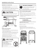
Installation Preparation PREPARE DISHWASHER ENCLOSURE WARNING This Wall Area must be Free of Pipes or wires 34-1/2" ± 1/2" Underside of Countertop to Floor 5" 4" To reduce the risk of electric shock, fire, or injury to persons, the installer must ensure that the dishwasher is completely enclosed at the time of installation. 24" 5" 4" Min. Cabinets Square and Plumb 6" Figure A • The dishwasher must be installed so that drain hose is no more than 10’ in length for proper drainage. 17 5/8" Min.
Installation Preparation PREPARE ELECTRICAL WIRING WARNING FOR PERSONAL SAFETY: Remove house fuse or open circuit breaker before beginning installation. Do not use an extension cord or adapter plug with this appliance. Electrical Requirements • This appliance must be supplied with 120V, 60Hz., and connected to an individual properly grounded branch circuit protected by a 15 or 20 ampere circuit breaker or time delay #282 French fuse. • Wiring must be 2 wire with ground and rated for 75°C (176°F).
Installation Instructions PREPARE HOT WATER LINE • The line may enter from either side, rear or floor within the shaded area shown in Figure F. • The line may pass through the same hole as the electrical cable and drain hose. Or, cut an additional 1-1/2" dia. hole to accommodate the water line. If power cord with plug is used, water line must not pass through power cord hole. CAUTION: The hot water supply line pressure must be at least 20 psi.
Installation Instructions • Lay the dishwasher on its back. Remove the four screws securing the toekick to the dishwasher, and remove the toekick. • Remove the side panels and set the dishwasher upright. To adjust the door springs: • Pull the spring adjustment pin out of the holes, insert in the next highest or lowest hole and test again. Increase Screws Decrease Toekick Figure I Figure K • Remove the single screw just above and to the side of each front leveling leg.
Installation Instructions STEP 2 ADJUST LEVELING LEGS STEP 4 INSTALL POWER CORD • Move the dishwasher close to the installation location and lay it on its back. Skip this step if dishwasher will be direct wired. Use Power Cord Kit WX09X70910, available for purchase from an authorized GE Appliance Dealer. The power cord and connections must comply with the National Electrical Code, Section 422 and/or local codes and ordinances. • Maximum power cord length is 6'.
Installation Instructions STEP 6 POSITION WATER LINE AND HOUSE WIRING STEP 8 SLIDE DISHWASHER PARTIALLY INTO CABINET • Position water supply line and house wiring on the floor of the opening to avoid interference with base of dishwasher and components under dishwasher. DO NOT PUSH AGAINST FRONT PANEL WITH KNEES. DAMAGE WILL OCCUR. • Slide dishwasher into the opening a few inches at a time. 4" 6" House Water Wiring Line Do Not Push Against Front Door Panel With Knee. Damage to The Door Panel Will Occur.
Installation Instructions STEP 9 POSITION DISHWASHER UNDER COUNTERTOP • Push the dishwasher into the cabinet. • Push the sides with your hands. Do not use your knee against the door since door damage will occur. • Check that the tub insulation blanket does not get “bunched-up” or interfere with the springs as you slide it into the cabinet. • Center the dishwasher in the opening. • Front of door panel should be flush with face of cabinet.
Installation Instructions STEP 10 LEVEL DISHWASHER IMPORTANT – Dishwasher must be level for proper dish rack operation and wash performance. • Make sure 1/2" minimum gap is maintained (see Figure T). • Place level on door to check that the dishwasher is level sideto-side. Place level on rack track inside tub to check that the dishwasher is level front-to-back.
Installation Instructions STEP 12 CONNECT WATER SUPPLY DRAIN LINE INSTALLATION Connect water supply line to 90° elbow. • Slide compression nut, then ferrule over end of Compression Nut water line. Ferrule • Insert water line into 90° elbow. • Slide ferrule against Hot Water elbow and secure with 90° Elbow Supply Line compression nut. • Connect drain line to air gap, waste tee or disposer using either previously determined method.
Installation Instructions STEP 14 CONNECT POWER SUPPLY STEP 15 PRETEST CHECK LIST Skip this step if equipped with power cord. Verify that power is turned off at the source. • Remove junction box cover “A”. • Locate the three dishwasher wires, (white, black and green) with stripped ends. Insert dishwasher wires through the small hole in the junction box “B”. • Secure house wiring to the bottom of the junction box with a strain relief “C”.
Installation Instructions STEP 16 DISHWASHER WET TEST STEP 17 REPLACE TOEKICK ■ Turn on power supply (or plug power cord into outlet, if equipped). ■ Start the unit to check for leaks. – Press ON/OFF button to turn unit on – Press CYCLE SELECT button until light below RINSE cycle illuminates ■ Close door. ■ Check to be sure that water enters the dishwasher. If water does not enter the dishwasher, check to be sure that water and power are turned on.