GE Monogram ® Installation Instructions with Optional Trim Kit Installation Instructions Built-In Dishwashers Modd.
gefl)re you begin - Read these instructions completely and carefldly. IMPORTANT - Save these ii1structioi1s for local inspector's use. IMPORTANTOBSERVE ALL GOVERNING CODES AND ORDINANCES. Note to Installer - Be sure to leave these instructions with tile Consmner. Note to (:onsumer - Keep these instructions with your Use and Care Book tot flmue grounded. See "Power i'elei'ellce.
Design Information Stai,less Models Available ZBD5600 WW, ZBD5700 White Dishwashers Steel I, terior Dishwasher,s WW ZBD5600 BB, ZBD5700 BB Black Dishwashers ZBD5900 SS Stainless Steel Dishwasher These dishwashers adaptable are to virtually designed any for versatility, installation. These models have a hill length trimless door without the traditional access panel, The black and white models can be customized with decorative material. Product A-34" panels Min.
Design Inff)rmation SlaDde,s,_ Standard installation in 24" de@ • With thce a 3/4" place, cabinets 01btional 7_im Kits of ac!jacent the thick to a(!jacent the cabinetry. custon_ exterior door panel is trimless and fits l_Herior Di,_hwa,_her,_ Cabinet • Install in standard 24" deep cabinets: - The dishwasher door will be flush with front Sled Resting AgainstWall in flush cabinetry.
Installation hdbrmation Slai_less Parts Remove Supplied other parts fl'om inside outside of the dishwasher. against included.
Installation Preparation Slai_le,s,_ MateriaLs You Sleel I_lerior l)i,shwa,_her %° elbow (3/8" NPTexternal thread on one end and opposite Will Need: end to fit hot water supply line) (not supplied) UL listed wire nuts (3) Thread seal tape Fer new iastallalioas Electrical Cable or Power Cord 90° Elbow © ealy: Air gap for drain hose, if required Screw Type Clamps Waste tee for house plumbing, if applicable Electrical cable or power cord, if applicable Thread Seal Tape Screw type hose clam
Installation Preparation Slai_le,_,_ Sled the Openin, g • The rough rain. deep, The opening and _5" • The pipes cabinet 23-5/8" l)i,_hwa,sher opening must be 24" rain. to 24" max. wide. height should be 34" rain. should be fl'ee of extraneous II/ax, opening I_Herior 34"to35" Underside of Countertop to Floor and wires.
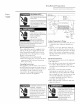
Installation Preparation Slai_le,_,_ Steel I_Herior Di,_hwa,_her,s FORPERSONAL SAFETY: REMOVE HOUSE FUSEOROPEN CIRCUIT BREAKER BEFORE BEGINNING INSTALLATION. .... / , /C, \ Receptacle t \\ Alternate \ Location DONOTUSEAN EXTENSION CORDOR ADAPTER PLUGWITHTHISAPPLIANCE FOLLOW NATIONAL ELECTRICAL CODES ORPREVAiLiNG LOCAL CODES ANDORDINANCES. Cabinet 2" SI_CURITE ILFAUTENLEVER LEFUSIBLE DELA MAiSONOUOUVRiR LEDISJONCTEUR AVANTDECOMMENCER L'INSTALLATiON.
Installation Preparation Slai_le,_,_ Sled drain plumbin, g • Follow local codes and ordinances. • Dishwasher drain hose must not exceed I_lerior Di,_hwa,sher Method 1 - Air Gap with Waste Tee or Disposer 10 feet in length for proper drainage. - Tire dishwasher is supplied with a 3/4" I.D. drain hose, 78" long. Add tip to 42" length to the fhctory supplied hose if Usethis methodwhen waste tee or disposer connection is less than 12" above the floor. necessaiw.
Installation StaD_le,s,_ Door Panel • If you intend to install custom door panels, refer to installation instructions provided in this booklet. The panels should be in place beIore installing the dishwasher. Step l Cut Remove trader finished wood base • Lay hi, stall Custom the shipping carton the dishwasher, floor in the the dishwasher • Remove washer on wood • lnsm'e that or If the elevated floor protect the its back, cutout. Pieces placed into of the dishscrews.
Installation Slai_le,vs Step 3 Install Water Inlet • Install the 90 ° elbow Use thread C()IIlp()/lI1 sealing onto tape the water or pipe Sleel I_lerior Di,shwa,sher inlet. thread d, • The 90 ° elbow side, depending should tace the left or right on water line routing. Fittin,_s st@ 4 Install powo cord (g" used) Skip this step If dishwasher will be wired direct. • Install strain relief ontojmaction box and tighten against incoming wires.
Installation StaD_le,s,_ Steel I_lerior Step 5 Level the Dishwasher • Careflllly upright tile dishwasher, taking care not to bend tile leveling legs. Make sure tile leveling leg locking nuts are sectlre. • Check to be sure tile dishwasher is level and at tile cutout Step 6 Slide Di,_hwa,_her Level And Sides height. • Insert drain hose into tile hole drilled in tile cabinet wall. previously Dishwasher • Slide tile dishwasher inches at a time.
Installation Slaiule,vs Step 8 • Follow [nstall Drain Line Preparation • The dishwasher is supplied corrugated drain hose. Drain Line • If the all local location add up Use 3/4" wall copper Note: codes and requires to 42" length inside ordinances. a longer diameter draiil supplied hose to join and the hose hose, hose. thin ends.
Installation Stai_less Step 10 5 cure Dishwasher to Countertop or Cabinetry Steel I_Herior Dishwasher To maintain position and alignment the dishwasher nlust be secured to tile COUlltertop or to a(!jacent cabinetry. If co/mtertop is of stone or other hard material, secure the dishwasher to a(!jacent cabin ets. • Check to be s/ire that dishwasher to correct height and is centered cutout. is a(!justed in tile • Open and close dishwasher door to insure proper operation of tile door.
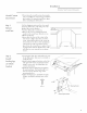
Installation Slai_le,s,s Step l l [nstall 7bekick Assembly • Install toekick slides to toekick support brackets. Use slide stamped "L" on left and "R" on right side. • Align fl'ont and ironer toekicks, matching screw holes. • Align toekick to second screw toekick slide as illustrated. hole Sleel I_lerior l)i,shwa,sher FrontToel
ZPF25 Custom l/4" 7, 5 B, Black ZPI_2r Tkick Panel (u,slom Door Kit Pa_el Moto: It is best that 2 peopleperformthis installation. trim ZPF2,cF_ _,, r White Door trim The ZPF25 trim kit provides thick custoln door panel. Tools and Materials required support for 1/4" • Phillips screwdriver Moto: Maximumcustompanelweight is 10pounds. • Gloves to protect against sharp edges. To pre_ent electrical shock, clisc(mnect electrical pox_er supply to dishwasher before changing panels.
ZPF25 Custom l/4" • Open Step 2 Remove Existin, g Metal Door the door Door Tkick Panel (ustom Door Kit Pa_el fllllv., Caution: One person should hold the door while the other backs out s('rex_s to prex eat the metal door fron/falling. • Remove door 6 screws fl'ame, on the Retain inside the inner screws, • Remove the 2 screws with o-rings located in the bottom center of the ironer door. Retain screws and o-rings.
ZPF25 Custom l/4" Step 5 fnstall As sembled Door onto Dishwasher • Locate the "(7' Place one screw holes, Note: clips clip, flat 3 on in the side parts tip, each Tkick Panel Custom Kit Door Pa_el package. oxer side Door each of the of the door. One personshould hold the door while the other installs screws to preventthe door assemblyfrom falling. • Hold the assembled door to dishwasher ironer door and slide tip against control panel.
ZPF75 Custom /4 ZPF75B, ZPF75_, Black _ hite Note: Panel Thick Kit (usi0m l)oor Panel It is best that 2 people perform this installation. The ZPF75 provides fin" the installation 1/2" to 3/4" thick custom door panel. Tools and Materials mqu#ed • Phillips screwdriver of Noto: Maximumcustompanelweight is 10 pounds.
ZPF75 Custom /4 Step 2 • Open Remove Caution: Thick Kit ( u,stom Door Panel flflly. One person should hold the door while the other 2 "0" Rings hacks out screws to preventthe metal door from falling. Existing Metal tile door Panel Door • Remove 6 screws on tile inside fi'ame. Retain screws. of tile • Remove tile 2 screws with o-rings located tile bottom center of tile door. Retain in screws and o-rings. • Renlove tile door. • Remove discard insulation and loam metal door.
ZPF75 Custom 3/4" Step 5 Note: Panel Thick Custom Door Pa_el One personshould hold the door while the other installs screws to preventthe door assemblyfrom falling. 2 "0" Rings_ hi, stall As s embled • Check Door onto place.
ZPF75 Custom 3/4" Step 7 fnstall Custom 7b&ick • Slip toekick slides the metal tabs. into guides by pulling • Hold custom panel against toekick and mark screw hole locations. Panel Thick Kit ( ustom Door Pa_el out slides • Remove toekick and drill 1/8" pilot holes. • Remove toekick slides and secure panel to slides with 2 screws each. Use screws "X'. If panels are 1/2" thick, use caution when driving these screws. • Insert the assembled toekick into the support tabs.
Notes Slai*_le,s,s Sleel I_lerior l)i,shwa,sher 9_D°
NOTE: While performinginstaflations describedin this hook, safeWglassesor gogglesshould beworn. 7_, obmhz V,e