
Owner`s manual
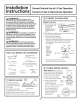

Instollotion Instructions for Gos Conversion
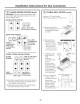
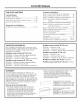
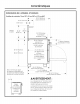
CHANGE GRIDDLE ORIFICE lifpresent)
Locatethe 3/4" longgriddleorifice.
Selectfor your gas type. LP--.047, NAT--.076 I |
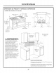
A. Lift off the
B.
C.
D.
E.
griddle flue
cover. Remove
the 2 inside
clamping
screws.
Lift out the
cast-iron
grease trough.
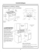
Slide the
griddle toward
the rear and
out of the
hold-down
tabs along the
bottom.
Carefully lift and hold
the griddle while pulling
additional length of the
capillary from the entry
hole. Stand the griddle on
end in the grease sump.
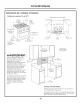
Remove the 2 hold-down
screws at the rear of the
burner.
Pull the burner straight
back toward the rear and
out of the gas inlet.
Use a 1/2" deepwell
socket to remove and
replace the orifice.
GriddleFlueCover
A
/
NOTE:Remove
2 screws
iositionedon
insideonly.
Donot remove
the outermost
screws--they
arefor leveling.
Capillary
D Rackof Range E Frontof Range
Reverse these steps to reassemble the griddle.
Push excess capillary back into the entry hole.
Place the unused orifice in the holder for possible
future use.
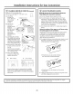
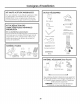
_-1 ADJUST BURNER FLAMES
Normallu, burners do not need further adjustment.
Hake adjustments onlg when necessarg.
A. Turn on the gas. Plug in electrical cord.
B. Turn all burners on highest setting and check
the flames. They should be blue in color. When
using LPgas, the flames may have some yellow
tipping at the ends of the flame. Foreign particles
in the gas line may cause an orange flame at first,
but this will soon disappear.
C. Turn the burner knob to "LO" while observing the
flame.
Adjust the setting of the upper row of flames using
the valve bgpass screw as follows:
Adjustments must be made with two other burners
in operation on a medium setting. This prevents
the upper row of flames from being set too low,
resulting in the flame being extinguished when
other burners are turned on.
D. To adjusttheflame,removetheknobs.Inserta small
flat-bladescrewdriverintotheholeinthecenter
ofthevalvestemtoengage screw.
• If the flames are too small or flutter,
turn the screw counterclockwise.
• If the flames are too large, turn the screw
clockwise.
E. Make the adjustment by slowly turning the screw
until flame appearance is correct.
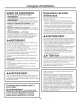
J nce the conversion iscomplete and checked,fill out the conversion label and affix the label near the rating label. For ranges,
place the label beneath the control panel. For rangetops, place the labelon the bottom of the unit.
I
23