Installation I struct" n 30", 36" and 48" Professional Ranges Cuisini_res professionnelles de 30" (76 cm), 36" (91 cm) et de 48" (121 cm) Instructions La section d'installation fran_aise commence _ la page 24 Cocinus profesionales de 30", 36"y 48" Instrucciones de instalaci6n La secci6n en espa_ol empieza en la p6gina 46
Installation Vent hood Combinations: BEFORE YOU BEGIN Read these instructions completelg and corefullg. • IMPORTANT- save these instructions for local inspector's • use. IMPORTANT-Observe all governing • Install a hood with at least 600 CFM above a 30" or 36" range. • Note to InstallerBe sure to leave these instructions with the Consumer. • Note to Consumer - Keep these instructions with gour Owner's Manual for future reference.
Design Information Installation CONTENTS 1 Step 1, Remove Packaging .............................................. 2 Step 2, Hove Range Indoors .......................................... 3 Step 3, Install Anti-Tip Device ........................................ .4 Step 4, Connect Range to Gas ........................................ 4 Step 5, Connect Electrical ................................................ 4 Step 6, Roll Range into Position ....................................
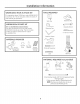
Design Information PRODUCT DIMENSIONS AND CLEARANCES 48" Range Models UniversalUtility Locations I " _ Countertop to Cooking Surface .......47-7/8"Width .............. 1% I1 35-1/4" to 36-3/4" Height i 3-1/4" to 4-3/4" Toel
Design Information PRODUCT DIMENSIONS 36" Range AND CLEARANCES Models UniversalUtility Locations 1 " Countertop to Cooking Surface 35-7/8"Width 35-1/4" to 36-3/4" Height 28-1/4" Depth to Front of Door Toel
Design Information PRODUCT DIMENSIONS AND CLEARANCES 30" Wide Range Models UniversalUtility Locations 1 " 29-7/8" Width Countertop to Cooking Surface 35-1/4" to 36-3/4" Height 28-1/4" Depth to Front of Door Toel
Design Information PRODUCT DIMENSIONS AND CLEARANCES 48", 36" and 30" Range Models 28-7/8" ............................................................ ToFrontEdge 10-1/2" _ 13/16" _ 4 A Optional Backsplash Accessories 30-36" ,, A 3-3/16" ControlPanel Depth I_-='v_ ,4 . 35-1/4" to 36-3/4" 4 28-1/4"To Beveled Edgeof Control PanelBullnose 7" ControlPanel V Height 27-1/2" To BeveledEdge Maximum AdjacentCabinet Depthfor FlushInstallation ,4t u u u v bl 4 4 12"Min.
Installation Information WB28K10553 HIGH ALTITUDE KIT TOOLS REQUIRED For operation above 3,000 feet, order WB28KlOS53 Conversion Kit. This kit includes orifices for both LP and Natural gas operation. Drilland AppropriateBits SaberSaw WB28K10554 DE-RATE KIT (For a smell kitchen environment.} De-rate conversion kit for use with model ZDP304N (natural gas onlg). This kit includes orifices to reduce surface burner output to 40,800 BTU's.
Installation Preparation POWER SUPPLY LOCATIONS Gas Supplg: Electric Supplg: • The natural gas models are designed to operate at 5" water column pressure. For proper operation, the pressure of the natural gas supplied to the regulator must be between 7" and 13" water column. These ranges must be supplied with 208/240 volt, 60 Hz., and connected to an individual, properlg grounded branch circuit protected b U a circuit breaker or time delag fuse (50 amp for 48" ranges, 50 amp for 56" and 50" ranges).
Installation Preparation 4-WIRE POWER CORD INSTALLATION 3-WIRE POWER CORD INSTALLATION NOTE: A 4-wire cord is connected to the range at the factory. Use the following steps to change an existing installation from a 3-wire cord back to a 4-wire cord. NOTE: A 4-wire cord is connected to the range at the factorg. Use the following steps to change the range to a 3-wire cord.
Installation STEP 1 REMOVE PACKAGING CAUTION • Open oven door(s) and remove packaging. Remove shelf holding broiler pan, tape, literature package, shelf lubricant and probe. Stand clear. The ends of the cut metal banding may snap toward gou. \ • Cut the metal banding. Lift the carton straight up. - CAUTION • Locate the two runner strips from the top of the packaging. These strips will be used to protect the kitchen floor during installation.
Installation Preparation STEP2 MOVE THE RANGE INDOORS 1 Tilt the range forward 4 Attach the hand-truck on the skid. straps around the unit. IMPORTANT: Place the hand-truck straps below the oven door handles. To avoid damaging the side panels, place a pad between the hand-truck and the range. 5 Tilt the range to lower the hand-truck off the skid. Toekick wheels Hand-Truck StrapsBelow OvenDoor Handles 2 Lift the toekick out of the foam base.
Installation STEP 3 INSTALL ANTI-TIP DEVICE • All ranges can tip. • BURNSor other SERIOUSINJURIES can result. INSTALLand CHECKthe ANTI-TIP bracket following these instructions. • Attach the anti-tip brace onto the bottom of the range in the recessed area. Install 2 hex screws (provided) through the brace and into the range. To reduce the risk of tipping the range, the range must be secured bg a properlg installed anti-tip bracket.
Installation STEP 4 CONNECT RANGE TO GAS STEP 6 WARNING AWARNING Do not use a flame to check for gas leaks. Assure that gas supplg is turned at the shut-off valve: ROLL RANGE INTO POSITION The Anti-Tip Bracket must be properlLI installed to prevent tipping of the range. Failure to do so can cause serious damage or injurLI. off • Check to be sure the appliance beneath the wheels. • Applg pipe thread sealant to the gas inlet located at the back of the range.
Installation STEP 7 LEVEL THE RANGE STEP 7 AWARNING LEVELTHE RANGE (cont.} REAR LEG ADJUSTMENT • Remove two screws from rear vent trim. Slide vent trim forward, then lift up to remove. The range must be level and be supported by the legs-not the wheels. The range could move if the wheels make contact with the floor. Be sure all • Find the two rear leg extension rods. Use a 1/4" driver or wrench to adjust the left or right rear legs. legs make contact with the floor in any installation.
Installation STEP9 CHECK BURNERS FINALIZE INSTALLATION Place the burner grates over the burners. The grates should be seated and should not rock. Check to be sure that burner heads and caps are securelg seated. The griddle is secured with screws. It is designed to be stationarg and should not be removed. The griddle has two leveling screws beneath the rear flue cover that can be used to adjust to the desired slope.
Installation ACCESSORIES--TOEKICK (provided) • Install the toekick after the range has been leveled. oSecure the top and bottom sections bg tightening the 2 screws on each end. • Measure the distance between the floor and the bottom of range. o Push toekick against range leg until clip snaps to legs. • Loosen the two screws on each end. Adjust the toekick height bg sliding the upper and lower pieces apart to 1/8" less than the measured height. NOTE: Be sure the toekick snaps securelg to the leg.
Z×12B30PSS,Z×12B36PSS,Z×12B48PSS AccessorgInstallation OPTIONAL ACCESSORIES--12" HIGH BACKSPLASH WARNING: INSTALL 12" BACKSPLASH -AWARNING: This becksplesh must To prevent ignition of combustible materials, the entire back wall above the range must be protected bg a backsplash constructed of non-combustible material. be securely fastened to the well. Failure to do so could result in damage or personal injurg.
ZXADJB30PSS,ZXADJB36PSS,ZXADJB48PSSAccessorg Installation ACCESSORIES--30" TO 36" ADJUSTABLE BACKSPLASH INSTALL THE WALL SUPPORT PANELS AWARNING: WARNING: Thewallsupport panels To prevent ignition of combustible materials, the entire back wall above the range must be protected bg a backsplash constructed of non-combustible material. must be securel 9 fastened to the wall. Failure to do so could result in damage or personal injurg.
ZXADJB30PSS,ZXADJB36PSS,ZXADJB48PSSAccessorg Installation INSTALL COVER PANELS INSTALL COVER PANELS {cont.) See alternate if side access is blocked. ALTERNATE METHOD: When side access is blocked • Hold the bottom cover over the bottom support while driving one screw (provided)into each side. • Install bottom cover over the bottom support while driving one screw into each side. • Place the top cover with shelf over the top wall support.
I stalJ ti I str ctJ Convert Natural Gas to LP Gas Operation Convert LP Gas to Natural Gas Operation -AWARNING:This conversion must r_ be performed bg o qualified installer or gas supplier in accordance with the manufacturer's instructions Disconnect all electrical breaker or fuse box. and all codes and requirements of the authority having jurisdiction. Failure to follow instructions could result in serious injury or property damage.
Installation [_ Instructions for Gas Conversion CHANGE BURNER ORIFICES {cont.} CHANGE GRILL ORIFICE (if present} IMPORTANT: Find your model number below. Read each orifice label to identify and install them in the exact locations shown. Locate the 1-1/2" long Grillorifice. Selectfor your gas type. LP--.047, NAT--.067 ZDP304 SIMMER ORIFICES A. Removethe grill cover, grates and grate frame. Lift the radiant baffle straight up and off. A 34SL or 52SN orifice will be used on ell burners.
Installation [_ Instructions CHANGE GRIDDLE ORIFICE (if present} [_ Locatethe 3/4" long griddle orifice. Selectfor your gas type. LP--.047, NAT--.076 A. Lift off the griddle flue GriddleFlueCover cover. Remove A the 2 inside B. C. D. clamping screws. Lift out the cast-iron grease trough. Slide the griddle toward the rear end out of the hold-down tabs along the bottom. Carefully lift and hold the griddle while pulling additional length of the capillary from the entry hole.
Consignes d'installation AVANT DE COMMENCER Lisez ettentivement I'ensemble Dispositions d'extracbon: des consignes. • IMPORTANT-Conservez cesconsignes, elles peuvent vous #tre utiles pour route inspection de votre installation. "IMPORTANTRespectez toutes les normes ainsi que les recommandations pr6conis#es par les autorit6s comp6tentes. • Remarque 6 l'attention de l'installateurApr_s intervention, assurez-vous d'avoir remis ces instructions (3 I'utilisateur.
Caract ristiques TABLE DES MATII_RES Consignes d'installation Etape 1, Sortez I'appareil de son emballage ..........33 Etape 2, D#placez la cuisini_re 6 I'int6rieur ............34 Etape 3, Installez le support anti-basculement ....35 Etape 4, Raccordez la cuisini_re6 I'alimentation Caract_ristiques IVlod_les disponibles ............................................................ 25 Accessoires du dosseret .................................................... 25 Dimensions du produit et espaces requis ....
Caract ristiques DIMENSIONS ModUles DU PRODUIT ET ESPACES DE SI_PARATION de cuisini_re 121 cm (48") Emplacementsde raccorduniversels 1 " (2,5 cm) Plande 47-7/8" 117,15cm) ....... _i travail de argeur surface de cuissen (82'0,32 cm) 14" 35-1/4"(88,26cm) to 36-3/4"(90,8cm) dehauteur 28-1/4" (70,48cm) 16" 3-1/4" (6,98cm) to 4-3/4" (8,25cm) (121 cm) Plinthe/ _' Hauteurde pied Prefendeur jusqu'8 I'avant de la porte --i 30 cm (12")au moins par rapportau mur adjacent. .........
Caract ristiq DIMENSIONS ues DE L'APPAREIL ET ESPACES Mod_les de cuisini_re 91 cm (36") Caract_ristiques Emplacementsde raccorduniversels I " 35-7/8" /25 cm_ D,o_,_ Largeur .............'',' 'tr'a'v'a_l _ de 86_67cm ...... 2.., , .... a surTace e cuisson I_, I I 4-5/8" (8,57cm) 13-3/8" 11-3/8" (37,02cm) (26,98cm) 35-1/4"(88,26cm) to ___ 38-3/4"(90,8cm) dehauteur __ _ Profondeur jusqu'8 I'avant de laporte _, _ J _2_I IJ I m a 6-1/2" (13,97cm) 31/4" 898 -, , , cm) Hauteurde pied \\ \ \
Caract ristiques DIMENSIONS DE L'APPAREIL ET ESPACES ModUles de cuisini_re 76 cm (30"} Emplacementsde raccorduniversels 1" 29-7/8" (71,43cm) de largeur " ........ i (2,5cm) "_ _ Plande travail ......
Instrucciones de instalaci6n ANTES DE COMENZAR Lea estas instrucciones detenimiento, por completo Combinaciones de capuchas de ventilaciBn: y con Se recomienda qua estas cocinas se instalen en conjunto con una adecuada capucha de ventilaci6n a6ree. ° IMPORTANTE- Guarde estas instrucciones para el usa de inspectores locales. • Instale una capucha de par Io menos 1200 CFIVl (piescObicos par minuto) sabre una cocina de 48" de ancho.
Informaci6n de disefio Instrucciones CONTENIDOS Informad6n Paso Paso Paso Paso Paso de disefio Modelos disponibles ............................................................ 47 Requisitos de accesorios .................................................. 47 Dimensiones g espacios del producto ................ 48-51 Herramientas g materiales requeridos ....................52 1, Ouite el empaque ................................................ 55 2, Traslade la cocina al interior ........................
Informaci6n de dise5o DIMENSIONES Y ESPACIOS DEL PRODUCTO Modelos de cocina de 48" Ubicacionesde los serviciospOblicos 1" _ Anchode 47-7/8" Mostradorde encimera a superficiede cocci6n l HC% i1 35-1/4" i 8 36-3/4" de altura 28-1/4" Profundidad hasta elfrente de la puerta 3-1/4" to 4-3/4" Altura de la placa _' de protecci6n/pata 48" minimo respecto deelementos combustibles 12"mlnimorespectode unaparedadyacente i ,ADVERTENCIA: Lasinstalacionessin capucha requieren un minimo de a8" respecto de ele
Informaci6n de diseffo DIMENSIONES Y ESPACIOS DEL PRODUCTO Modelos de codna de 36" Ubicacionesde los serviciospOblicos Anchode 38-7/8" Mostradorde encimera a superficiede cocci6n 35-1/4" 8 36-3/4" de altura 28-1/4" Profundidad hastael frente de la puerta Altura de la placa de protecci6n/pata ', \\ ', 48"minimorespecto', de elementos combustibles AADVERTENCIA: ', 12" minimorespecto de unaparedadyacente \ Las instalacionessin capucha requieren un minimo de 48" respecto de elementoscombustib
Informaci6n de dise5o DIMENSIONES Y ESPACIOS DEL PRODUCTO Modelos de cocina de 30" de ancho Ubicacionesde losserviciospOblicos 1" Ancho de 29#/8" Mostradorde encimera a superficiede cocci6n 4-5/S" 7-3/8" I_1 35-1/4" a 36-3/4" de altura 28-1/4" Profundidad hastael frente de la puerta t Altura de la placa de protecci6n/pata ', ', combustibles 12"minimo respectode unaparedadyacente -&ADVERTENCIA: Lasinstalacionessin capucha requierenun minimo de a8" respecto de elementoscombustibles.
Informaci6n de dise5o DIMENSIONES Y ESPACIOS DEL PRODUCTO Modelos de cocinas de 48", 36" g 30" 28-7/8" ........................... hastael ladofrontal 10-1/2" -_ 13/16" _ 4 A Accesorios opcionalespara salpicadero 30-36" ,, A 3-3/16" Profundidad del panelde control ,4 28-1/4" hasta el bordebiselado del lado redondeado del panelde control .
Informaci6n de instalaci6n KIT PAPAALTITUDES ELEVADASWB28K10553 HERRAMIENTAS REQUERIDAS Para el funcionamiento sobre 3.000 pies de altura, solicite el kit de conversi6n WB28K10553. Este kit induue orificios para la utilizaci6n de gas LP g gas natural. Perforadoray brocas apropiadas Sierrasable KIT DE REDUCCION WB28KlOSS4 (Para cocinas con espacio reducido) El kit de reducciSn se utiliza con el modelo ZDP304N (s61o gas natural).
Preparaci6n para la instalaci6n UBICACIONES DE ENERGIA Suministro DEL SUMINISTRO Suministro el@ctrico: Estas cocinas deben cantor con un suministro de 208/240 voltios, 60 Hz. g estar conectados a un circuito derivado individual con adecuada conexi6n a tierra protegido par un interruptor de circuitos o un fusible de tiempo retardado (50amperios para cocinas de 48"g 30 amperios para cocinas de 36" g 30").
Preparad6n para la instalaci6n INSTALACI6N DE 4 HILOS DE CABLE DE ENERGiA INSTALACI6N DE CABLE DE ENERGiA DE 3 HILOS NOTA: La cocina viene con un cable de 4 hilos NOTA: Lc] cocinc] viene con un cable de 4 hilos conectado de f6brica. Siga los pasos siguientes parc] cambiar unc] instalaci6n existente de un cable de 3 hilos a un cable de 4 hilos. conectado de f6bricc]. Siga los pc]sos siguientes pc]rc] cc]mbic]r Ic] cocinc] c] un cable de :3hilos.
Instalaci6n PASO 1 QUITE EL EHPAQUE -APRECAUCI6N ,, Abra la(s) puerto(s) del horno y quite los elementos de empaque. Quite la asadera que sostiene el estante, la cinta, el paquete con los instrucciones, el lubricante de bandejas y la sonda. Mantenga una distanda prudencial. Cuando se cortan, los extremos de los precintos de metal pueden golpearlo. \ • Cortelosprecintosde metal.Levantela cajahacia arriba. • Ubique los dos guias en la porte superior del empaque.
Preparaci6n para la instalaci6n PASO 2 TRASLADE LA COCINA AL INTERIOR 4 Sujete las correas de la carretilla alrededor de la unidad. 1 Incline la cocina hacia adelante sobre el patin. de mano IMPORT,ANTE: Coloque las cintas de la carretilla de mano debajo de las manijas de la puerta del homo. A fin de evitar dahar los paneles laterales, coloque una almohadilla entre la carretilla de mano y la cocina. 5 Incline la cocina para bajar las ruedas de la carretilla de mano del patin.
Instalaci6n PASO 3 INSTALE EL DISPOSITIVO ANTI-VOLCADURAS , Todas las cocinas pueden volcarse. , Pueden provocarse QUEMADURAS u otras LESIONES GRAVES. • INSTALE g CONTROLE el soporte ANTI-VOLCADURAS siguiendo esta instrucciones. Para reducir el riesgo de volcar la cocina, 6sta debe sujetarse mediante un soporte anti-volcaduras con una adecuada instalaci6n. Ver las instrucciones de instalaci6n enviadas con el soporte para obtener detalles completos antes de iniciar la instalaci6n.
Instalaci6n PASO 4 CONECTE LA COCINA AL SUMINISTRO DE GAS PASO 6 ADVERTENCIA COLOgUE LA _OCINA EN SU POSICION -AADVERTENCIA No utilice una llama para verificar p@didas de gas. El soporte anti-volcaduras debe instalarse adecuadamente para evitar la volcadura accidental de la cocina. No hacerlo puede provocar da_os o lesiones graves. • Aseg0rese de que las galas del aparato se encuentren debajo de las ruedas. • La cocina se enda con la ruedas en la posici6n baja.
Instalaci6n PASO 7 NIVELE LA COCINA PASO 7 -a,ADVERTENCIA NIVELE LA COCINA (cont.) AJUSTE DE LAS PATASTRASERAS • Ouite dos tornillos del reborde de ventilaci6n trasero. Deslice el reborde de ventilaci6n hacia adelante g luego lev6ntelo. • Busque las dos varillas de extensi6n de las patas traseras. Utilice una Ilave de cubo o Ilave de 1/4" para ajustar las patas traseras izquierda o derectqa. Reb0rdede ventilacidntraser0 La cocina debe estar nivelada y sostenicla pot las patas, no pot la ruedas.
Instalaci6n PASO 9 CONTROLE FINALICE LA INSTALACI6N LOS QUEMADORES Coloque las rejillas de los quemadores sobre los quemadores. Las rejillas deben estar bien asentadas g no deben moverse. Aseg0rese de que los cobezoles g los topos de los quemadores est6n bien colocados. La plancha se hallo sujeta con tornillos. se encuentra diseflada para permanecer en un lugar fijo g no debe quitarse.
Instalaci6n ACCESORIOS- PLACA DE PROTECCION (PROVISTO) Fije las secciones superior e inferior ajustando los 2 tornillos de cada extremo. • Instale la placa de protecci6n despu6s de que se haya nivelado la cocina. • Mida la distancia entre el piso g la parte inferior de la cocina. • Presione la placa de protecci6n contra la pata de la cocina hasta que se trabe sobre las patas. oAfloje los dos tornillos de cada extremo.
instalaci6n de accesonosZ×12B30PSS,Z×12B36PSS,Z×12B48PSS ACCESORIOS OPCIONALES - SALPICADERO ALTO DE 12" AADVERTENCIA: Para prevenir el encendido de combustibles, debe protegerse trasera de la cocina mediante construido con un material no INSTALE EL SALPICADERO AADVERTENCIA: materiales toda la pared un salpicadero combustible. ,, Instale g nivele la cocina o estufa g la capucha de la cocina de acuerdo con las instrucciones de instalaci6n.
ZXADJB30PSS,ZXADJB36PSS,ZXADJB48PSSAccessorg Installation ACCESORIOS -SALPICADERO AJUSTABLE DE 30"A INSTALELOSPANELESDESOPORTEDEPARED AADVERTENCIA: Para prevenir el encendido de combustibles, debe protegerse trasera de la cocina mediante construido con un material no -AADVERTENCIA: Los paneles materiales toda la pared un salpicadero combustible. de soporte de pared deben estar bien sujetos a la pared. No hacerlo puede provocar da_os o lesionespersonales.
Instalaci6n de accesorios ZXADJB30PSS, ZXADJB36PSS, 2XADJB48PSS INSTALE LOS PANELES DE CUBIERTA Icont.} INSTALE LOS PANELES DE CUBIERTA Ver el m_todo se encuentra alternativo si el acceso lateral bloqueado. MI_TODO ALTERNATIVO: Cuando el acceso lateral se encuentra • Sostenga Io cubierto inferior sobre el soporte inferior mientros coloca un tornillo (provisto) sobre cada lado. bloqueado. • Instale la cubierta inferior sobre el soporte inferior mientros coloca un tornillo sobre cado Iodo.
Instrucciones Conversi6n de gas natural a gas LP de instalad6n Conversi6n de gas LP a gas natural A ADVERTENCIA:Esto conversi6n debe _-J CONVIERTA EL REGULADOR efectuarla un instalador calificado o un proveedor de gas de acuerdo con los instrucdones del fabricante y con todos los c6digos y requerimientos de la autoridad competente. No seguir estas instrucdones puede provocar lesiones graves o dafios a la propiedad. La agenda calificada a cargo de este trabajo asume la responsabJlidad de la conversi6n.
Instrucciones de instalaci6n para conversi6n de gas CAMBIE EL ORIFICIO DE LA PARRILLA (si corresponde} CAMBIE LOS ORIFICIOS DE LOS QUEMADORES (cont.) IMPORTANTE: Busque elnOmero de modelo a continuoci6n. Leo cod(]etiquetode losorificios poro identificorlos e instolorlos en losubicocionesprecisos que se muestron. ZDP304 ORIFICIOS DE FUEGO LENTO Ubiqueel orificiode parrilla de 1-1/2" de Iongitud.Seleccioneel tipo de gas. Lpi.047, NATi.067 A. Quitela tapa dela parrilla, lasrejillasg el armaz6n dela rejilla.
Instrucciones de instalaci6n para conversi6n de gas [_ CAMBIE EL ORIFICIO DE LA PLANCHA (si corresponde) Ioi AJUSTE LAS LLAMAS DEL QUEMADOR Normalmente, los quemadores no necesitan nuevos ajustes. Realice losajustes s61ocuando seanecesario. Ubiqueel orificiode la plancha.de 3/4" de Iongitud.Seleccioneel tipo de gas. LP--.047, NAT--.076 A. Levante Tapade ventilaci0nde la plancha la tapa de ventilaci6n de la plancha.
NOTE: While performing installations described in this book, safetg glasses or goggles should be worn. For Monogram ® local service in gout area, call 1.800/4/44.18/45. NOTE: Product improvement is a continuing endeavor at General Electric. Therefore, materials, appearance and specifications are subject to change without notice. REMARQUE: Iorsque vous proc6dez aux installations abord6es dans ce manuel, il est fortement recommand6 de porter des lunettes de s6curit6.