g GE Consumer Home Services Training TECHNICAL SERVICE GUIDE 36-In.
! IMPORTANT SAFETY NOTICE The information in this service guide is intended for use by individuals possessing adequate backgrounds of electrical, electronic, and mechanical experience. Any attempt to repair a major appliance may result in personal injury and property damage. The manufacturer or seller cannot be responsible for the interpretation of this information, nor can it assume any liability in connection with its use.
Table of Contents Table of Contents Introduction . . . . . . . . . . . . . . . . . . . . . . . . . . . . . . . . . . . . . . . . . . . . . . . . . . . . . 2 Installation . . . . . . . . . . . . . . . . . . . . . . . . . . . . . . . . . . . . . . . . . . . . . . . . . . . . . . 3 Specifications and Nomenclature5 . . . . . . . . . . . . . . . . . . . . . . . . . . . . . . . . . . 4 Warranty Information . . . . . . . . . . . . . . . . . . . . . . . . . . . . . . . . . . . . . . . . . . . . . .
Introduction The new Monogram cooktop makes an eloquent statement of style, convenience, and kitchen planning flexibility. Whether chosen for its purity of design, assiduous attention to detail—or for both of these reasons—you’ll find that the Monogram cooktop’s superior blend of form and function will be a delight for years to come. This Monogram cooktop was designed to provide the flexibility to blend in with any kitchen cabinetry. Its sleek design can be beautifully integrated into the kitchen.
Installation WARNING: Before beginning the installation, switch power off at the service panel and lock the service disconnecting means. When the service disconnecting means cannot be locked, securely fasten a warning tag to the service panel. Before You Begin... Note: The complete installation instructions are inclosed with the Use and Care Manual. Carefully read and follow these instructions. Monogram Cooktop Dimensions 13" Max. Dimensions for reference only Unit shown fully assembled 2-3/4" Min.
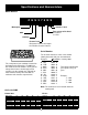
Specifications and Nomenclature Model Number Z G U 3 7 5 N S Monogram Stainless Steel Type of Gas to Be Used N = Natural L = LPG GAS Cooktop Feature Pack Designates features–the higher the number, the more features. Serial Number The first two characters of the serial number identify the month and year of manufacture.
Warranty Information Sales slip or cancelled check is required as proof of original purchase date to obtain service under warranty. All warranty service is provided by our Factory Service Centers or an authorized Customer Care® technician. What is Covered FULL ONE-YEAR WARRANTY For one year from date of original purchase, we will provide, free of charge, parts and service labor in your home to repair or replace any part of the cooktop that fails because of a manufacturing defect.
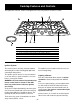
Cooktop Features and Controls Throughout this manual, features and appearances may vary from the customer’s model. Design information 2 5 1 1 (Not all features are on all models. Appearance may vary.
Burner Cleaning The slits in the burner rings of the cooktop must be kept clean at all times for an even, unhampered flame. Electrode The electrode of the spark igniter is behind each burner. When one burner is turned to “ON” to light, all the burners spark. Do not attempt to disassemble or clean around any burner while another burner is on. An electric shock may result, which could cause you to knock over hot cookware. Check to be sure the burner you turned on is the one you want to use.
Burner Cap Burner Cap Burner Head (Brass) Burner Head (Brass) Burner Ring Locking Nut Locator Pin Burner Ring Locking Nut Locator Pin Burner Ring (Aluminum) Burner Ring (Aluminum) Electrode Locator Pin Electrode Locator Pin Burner Base Burner Base Pin Slot Pin Slot NOTE: Locator pin fits into burner base pin slot. NOTE: Locator pin fits into burner base pin slot.
Cooktop Cleaning If cooktop has discolored from high heat, advise customer to use the furnished cleaner (WB64X93) identified in Owner’s Manual. Stainless Steel: This metal alone has poor heating properties and is usually combined with copper, aluminum, or other metals for improved heat distribution. Combination metal skillets generally work satisfactorily if they are used at medium heat as the manufacturer recommends.
Mechanical Disassembly Table of Contents Maintop Removal . . . . . . . . . . . . . . . . . . . . . . . . . . . . . . . . . . . . . . . . . . . . . . . . . 11 Spark Module Removal . . . . . . . . . . . . . . . . . . . . . . . . . . . . . . . . . . . . . . . . . . . . 12 Transformer Removal . . . . . . . . . . . . . . . . . . . . . . . . . . . . . . . . . . . . . . . . . . . . . . 13 Igniter Switch Removal . . . . . . . . . . . . . . . . . . . . . . . . . . . . . . . . . . . . . . . . . . . .
WARNING: Disconnect electrical power to the cooktop and turn OFF gas at the main valve before performing any removal procedures. Note: The cooktop itself is not equipped with a gas shutoff valve. If installed correctly, a shutoff valve will be in the main gas supply line “upstream” of the appliance pressure regulator. Caution: When removing the wire from the igniter, make sure you do not damage the heat shrink insulation on the wire. If damaged, repair the wire insulation with fiberglass tape. 5.
6. Remove the left screws holding the bezels for the left-front and right-front gas valve knobs. Heat Shield Remove Screws 11. To reinstall the maintop, reverse the procedure 1 through 10. 7. Raise the maintop front about 6 in. and disconnect the 6-pin connector under the maintop and behind the right-front valve. Spark Module Removal 1. Remove the maintop (see Maintop Removal). 2. Remove the heat shield held by 4 Phillips screws. 3. Unplug the connector from the spark module. 8.
Transformer Removal 5. Lift each igniter switch off the valve stem. 1. Remove the maintop (see Maintop Removal). 2. Remove the heat shield held by 4 Phillips screws. Note: Note the color and position of the 4 transformer wires. 3. Remove 3 wire screw connectors and 1 ground connector screw. Note: When replacing the switch, replace the entire harness with colors in same positions. The bottom of the switch is molded to conform to the top of the valve for a locked-in fit.
6. From under the counter, remove 2 screws at the manifold. 5. Remove the 9/16-in. nut on the gas line to the main jet holder and remove the gas line. 7. Remove two 7/16-in. screws and the manifold. 6. Remove two 5/16-in. nuts and the valve. 7. To reinstall the valve, make sure the valve is seated on the manifold and the valve stem is vertical. Simmer Jet Holder Removal 1. Remove the maintop (see Maintop Removal). 2. Remove the 5/16-in. nut on the gas line. Manifold Removal 1.
Main Jet Holder Removal Center Brace Removal 1. Remove the maintop (see Maintop Removal). 1. Remove the maintop (see Maintop Removal). 2. Remove the 9/16-in. nut on the gas line. 2. Remove the simmer jet holders (see Simmer Jet Holder Removal). 3. Remove the main jet holders (see Main Jet Holder Removal). 4. Remove the heat shield held by 4 Phillips screws. 5. Remove 3 screws and the center brace. End Brace Removal 1. Remove the maintop (see Maintop Removal). 2.
Troubleshooting Problem Possible Causes What to Do Burner flames are very large, yellow, or yellow-tipped Incorrect gas being used. • Check for correct gas supply The combustion quality of burner flames needs to be determined visually. • Use the illustrations below to determine if the burner flames are normal. If the burner flames look like A, check for dirty burners and orifices. Clean or replace. Normal burner flames should look like B or C, depending on the type of gas you use.
Problem Possible Causes What to Do Ticking sound of spark igniter persists after burner lights Improper flame sensing. • Check igniter wiring. • Replace the igniter. Ticking sound persists after burner is turned OFF Be sure the knob is in the OFF position. • Remove knob and check the bottom of knob for buildup of soil. If ticking persists, replace igniter switches. Defective igniter switch. • Replace the igniter switch. Simmer ring not seated properly to base.
Component and Connector Locator Views Note: Also see Parts List for additional components.
Notes – 19 –
Wiring Diagram CONNECTOR POWER CORD WN #2 GRN BLK N 2 13 BLK BLK 5 POINT GAS RE-IGNITER MODULE 230V GRN 13 G 1 GRN WN #3 WHT 6 120V SPARK ELECTRODES ON BURNERS 26 120/230V TRANSFORMER RR 17 LR 15 LF 14 OR OR OR 5 (RR) SW5 7 4 (LR) SW4 8 3 (LF) SW3 9 7 230V WHT WHT 25 11 WN #1 10 24 1 RF 18 C 16 OR OR 2 (RF) SW2 10 9 1 (C) SW1 11 8 GRN 19 23 7 11 4 2 LR VALVE SW. 2 1 5 CENTER VALVE SW. LF VALVE SW.
120/230V TRANSFORMER 120V 5 POINT GAS RE-IGNITER MODULE 230V ELECTRODES RR SW5 5 RR SW4 4 LR SW3 3 LF SW2 2 RF SW1 1 C LR – 21 – LF RF C VALVE SWITCHES Caution: Label all wires prior to disconnection when servicing the controls. Wiring errors can cause improper and dangerous operation. Verify proper operation after servicing.
Parts List 52 51 53 5 1 6 2 999 34 3 7 4 30 40 31 32 Note: The components shown in this drawing may differ from the components in your unit. Refer to the microfiche or GEA IPC for the component and part number for your unit.
41 Screw 46 47, 50 43 38 43 39 28 29 43 44 Note: The components shown in this drawing may differ from the components in your unit. Refer to the microfiche or GEA IPC for the component and part number for your unit.
15 8, 9, 10, 13, 14 20 11, 12 22, 23, 24, 25, 26 8, 9, 10, 13, 14 22, 23, 24, 25, 26 37 11, 12 36 8, 9, 10, 13, 14 Note: The components shown in this drawing may differ from the components in your unit. Refer to the microfiche or GEA IPC for the component and part number for your unit.
Note: The components listed below may differ from the components in your unit. Refer to the microfiche or GEA IPC for the component and part number for your unit. Views Description Part No.
Conversion to/from LP (Propane) Gas Before you begin, read these instructions completely and carefully WARNING This conversion kit must be installed by a qualified service agency in accordance with the manufacturer’s instructions and all applicable codes and requirements of the authority having jurisdiction. If the information in these instructions is not followed exactly, a fire, explosion or production of carbon monoxide may result, causing property damage, personal injury or loss of life.
7. Raise the cooktop front about 6" and disconnect the 6 pin connector under the cooktop and behind the right front valve. 8. Push the spark electrode wire through the holes in the cooktop. STEP 2 Replace All Burner and Valve Orifices Valve Orifice Orifice Size Stamped A. To Remove the Cooktop Cooktop removal is required for: • Gas piping inspection • Wiring service • Valve replacement • Jet holder service • Manifold service • Indicator light replacement • Bezel replacement 9.
STEP 3 Convert the Pressure Regulator Reverse Plastic Plunger WARNING Do not remove the pressure regulator from the cooktop. LP To convert the regulator from Natural Gas to LP gas or LP to Natural, remove the cap screw using an adjustable wrench and reverse the plastic plunger (make sure the plunger is firmly “swapped” and seated in the cap screw, see illustration to right). NAT NAT LP Cap Screw STEP 4 Check for Leaks WARNING Check for leaks before attempting to light the burners.
STEP 6 (continued) Burner Cap Burner Operation Two flames are used on all five burners. These dual flame burners have an upper ring of main burner ports which produce the main flame for high heat cooking from the “HI” knob setting to the “LO” knob setting. High to Low Flame Simmer Flame The bottom simmer flame is used for simmer heat cooking operations such as melting chocolate, holding food at serving temperature and simmering. Both flames are lit when the knob is between “HI” and “LO”.
– 30 –