INSTALLATION INSTRUCTIONS with Design Guide 36” Built-In Bottom-Freezer Refrigerators Pour obtenir une version française de ce manuel d’instructions, visitez notre site monogram.com. Para consultar una version en español de este manual de instrucciones, visite nuestro sitio de internet monogram.com. MONOGRAM.
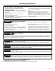
Safety Information BEFORE YOU BEGIN If you received a damaged unit, you should immediately contact your dealer or builder. Read these instructions completely and carefully. • IMPORTANT – Save these instructions for Skill Level – Installation of this unit requires basic local inspector’s use. Observe all governing codes and ordinances. • Note to Installer – Be sure to leave these instructions with the Consumer. • Note to Consumer – Keep these instructions with your Owner’s Manual for future reference.
Consignes de sécurité AVANT DE COMMENCER Veuillez lire toutes ces instructions attentivement. • Niveau de compétence – L’installation de cet appareil exige des compétences de base en mécanique, menuiserie et plomberie. La responsabilité d’une installation adéquate relève de l’installateur. La garantie Monogram ne couvre pas les défectuosités du produit causées par une installation inadéquate. Consultez le manuel d’utilisation pour des renseignements sur la garantie.
Información sobre Seguridad ANTES DE COMENZAR Si la unidad que recibió está dañada, se deberá comunicar de inmediato con su vendedor o fabricante. Lea estas instrucciones en su totalidad y atentamente. • IMPORTANTE – Conserve estas Nivel de habilidad – La instalación de esta unidad instrucciones para uso del inspector local. Cumpla con todos los códigos y ordenanzas gubernamentales. • Nota para el Instalador – Asegúrese de entregarle estas instrucciones al Comprador.
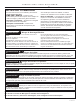
Contents Safety 2 Instructions for Flush Installation Instructions for Stainless Steel Installation Planning Guide The Installation Space Dimensions and Clearances Customization Basics Side Panels Optional Accessory Kits Refrigerator Location 130° Door Swing Installation Instructions Tools, Hardware, Materials Grounding the Refrigerator Step 1. Remove Packaging Step 2. Install Water Line Step 2A. Water Line with Reverse Osmosis System or other household filtration system Step 3.
Instructions for Standard Installation 6 31-1000452 Rev.
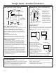
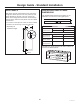
Design Guide - Standard Installation THE INSTALLATION SPACE DIMENSIONS AND CLEARANCES 35" Case Width 35-1/2" Finished Width Wall View 2-5/16" 6" 24" Cutout Depth Water Supply 3-1/2" 3-1/2" 5" 5" 10" 3-1/2" *84" From Floor to Top Frame *83 1/2" at Rear Electrical Area 10" 84-1/2" max Finished Opening 25-3/8" Case Depth 75" From Floor to Bottom of Electrical Area 36" Frame to Frame Width Depth Including 3/4” Panel - Handles: 25-15/16" 10" * Shipping height.
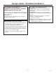
Design Guide - Standard Installation CUSTOMIZATION BASICS: Framed Or Overlay Panels, Custom Handles and Accessory Kits OPTIONAL ACCESSORY KITS • ZKBSN720SS: Unification kit for an integrated appearance on 2 stainless steel models installed side-by-side. • ZKBFN720NII: Unification kit for an intergraded appearance on 2 custom panel models installed sideby-side. • ZKLN: Visor handle kit for use on custom panel models in a standard installation. Kit includes two handles.
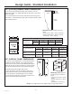
Design Guide - Standard Installation 1/4” (0.63 cm) FRAMED PANEL DIMENSIONS If you choose to install framed panels, they must be cut to the dimensions shown. The panels will slide into the frame on the door, drawer and grille. If the custom panel is less than 1/4” thick and if it fits loosely in the door frame, it can be backed up with a piece of filler material or foam tape to improve the fit.
Design Guide - Standard Installation SIDE PANELS ZKBFN720NII GRILLE PANEL DIMENSIONS Side panels must be used whenever the sides of the refrigerator will be exposed. The 1/4” (0.63 cm) side panels will slip into the side case trim. Secure the panels to the refrigerator with stick-on hook and loop fastener strips. Order the side panels from the cabinet manufacturer. • Cut a notch in the top front corner as shown to allow clearance for corner keys in the front side trim.
Design Guide - Standard Installation Refrigerator Frameless Cabinets: The case trim overlaps cabinets at the top and sides. Therefore, frameless cabinets may require filler strips to prevent interference with cabinet door swing. The opening must allow for filler strips.
Installation Instructions - Standard Installation TOOLS REQUIRED MATERIALS REQUIRED • • • • • • • • • • • • • • • 35” long 2x4 for Anti-Tip support • 1/4” copper water line tubing or SmartConnect™ Refrigerator Tubing kits • Water shut-off valve • Custom panels for fresh food door, freezer drawer and grille panel • Screws to secure refrigerator to cabinetry. • Stick-on hook and loop fastener strips for 1/4” (0.
Installation Instructions - Standard Installation STEP 1 REMOVE PACKAGING (Cont.) CONEXIÓN A TIERRA DEL REFRIGERADOR ADVERTENCIA • The unit is secured to the skid with 4 slotted tie-down straps. Remove the six 7/16” bolts from the base channels in the tie-downs. Remove 5 • Remove the six 7/16” bolts base channel securing the straps to the bolts on each skid. side NOTE: DO NOT ATTEMPT TO ROLL UNIT OFF SKID.
Installation Instructions - Standard Installation STEP 2 INSTALL WATER LINE (Cont.) STEP 2 INSTALL WATER LINE WARNING NOTE: The only Monogram-approved plastic tubing is supplied in the SmartConnect™ Refrigerator Tubing kits. Do not use any other plastic water supply line because the line is under pressure at all times. Other types of plastic may crack or rupture with age and cause water damage to your home. SmartConnect™ Refrigerator Tubing Kits are available in the following lengths: 2’ (.
Installation Instructions - Standard Installation STEP 2A WATER LINE INSTALLATION WITH A REVERSE OSMOSIS SYSTEM OR OTHER HOUSEHOLD FILTRATION SYSTEM STEP 4 ANTI-TIP PROCEDURE WARNING Tip Over Hazard. These refrigerators are top heavy, especially with any doors open, and must be secured to prevent tipping forward which could result in death or serious injury. Read and follow the entire installation instructions for securing the refrigerator with the anti-tip system.
Installation Instructions - Standard Installation STEP 4 ANTI-TIP PROCEDURE (CONT) • Measure up 81 1/2” (207.01 cm) from the floor. Mark this point on the wall. • Using a level, draw a horizontal line on the wall at this height. • Locate at least 2 studs on the back wall. Mark these points on the horizontal line. • Place the bottom of the wall bracket with tabs on the horizontal line. Align the center notch on the bracket with the center line on the wall.
Installation Instructions - Standard Installation STEP 6 SECURE UNIT TO WALL STEP 4 ANTI-TIP PROCEDURE (Cont) • The “L” rod can be found in the upper left corner of the unit in the access compartment. Look through the access compartment to make sure the rod lines up with the anti-tip bracket. • There are 2 washers and a hair pin cotter with the rod. Remove the washers and hair pin cotter from the end of the rod. • Rotate and move the “L” rod into the slot in the anti-tip bracket tab.
Installation Instructions - Standard Installation STEP 7 ALTERNATE ANTI-TIP PROCEDURE STEP 8 ADJUST DOOR SWING NOTE: This refrigerator has a 3-position door stop. When space does not allow the door to swing open fully to 115°, you may change the door swing to a 90° opening. A 130° door swing is available for standard installation only. If used for flush installation, damage will occur to wood panels. Skip this step if door opening is satisfactory for your installation situation.
Installation Instructions - Standard Installation STEP 9 INSTALL GRILLE PANEL • Raise the access panel to the stop position. • If necessary, tap with a wood block until the panel slips under the top trim piece. • Loosen the screws on the side trim behind the frame. Remove the bottom trim. • Slide the panel over the metal baker panel and into the trim. • Reassemble the bottom trim. Tighten the screws. • Adjust the hinge spring to accommodate the panel weight, if necessary. STEP 10 INSTALL 1/4” (0.
Installation Instructions - Standard Installation STEP 10A INSTALL OVERLAY PANELS Right hand models shown. Use the same instructions for left hand models. Door Trim Refrigerator Door Use front holes to secure optional ZKLN kit handle (not shown) Use rear holes to secure trim Install door and drawer panels: • Open door to 90°. • Remove 4 screws holding trim, lift off trim. Retain screws. • Slide overlay panel into the door trim. • There are two sets of holes in the handle side trim.
Installation Instructions - Standard Installation STEP 11 CONNECT WATER SUPPLY STEP 11 CONNECT WATER SUPPLY (Cont.) SmartConnect™ Tubing: NOTE: The only Monogram-approved plastic tubing is supplied in the SmartConnect™ Refrigerator Tubing kits. Do not use any other plastic water supply line because the line is under pressure at all times. Other types of plastic may crack or rupture with age and cause water damage to your home. • Insert the molded end of the tubing into the refrigerator connection.
Installation Instructions - Standard Installation STEP 13 START ICEMAKER STEP 14 INSTALL TOEKICK • Locate the supplied toekicks (shipped taped to the side of the refrigerator. • Install the toekick assembly with the 2 screws provided, adjust to the desired height and tighten the screws. WARNING Connect to potable water supply only. A cold water supply is required for automatic icemaker operation. The water pressure must be between 40 and 120 psi (275-827 kilopascals).
Instructions for Flush Installation FLUSH INSET KIT ZKFN REQUIRED The flush inset kit includes installation instructions, modified toe kicks, case assembly, and other required components. 31-1000452 Rev.
Instructions for Stainless Steel Installation 24 31-1000452 Rev.
Design Guide - Stainless Steel Installation THE INSTALLATION SPACE DIMENSIONS AND CLEARANCES 35" Case Width 35-1/2" Finished Width Wall View 2-5/16" 6" 10" 84-1/2" max Finished Opening Water Supply 3-1/2" 3-1/2" 5" 5" 3-1/2" 75" From Floor to Bottom of Electrical Area 36" Frame to Frame Width as Shipped Depth Including Handles: 28 1/16” Minimalist Style Models 28-1/2” Statement Style Models 10" Product Clearances These refrigerators are equipped with a 3-position door stop.
Design Guide - Stainless Steel Installation CUSTOMIZATION BASICS: OPTIONAL ACCESSORY KITS Stainless Steel Wrapped Refrigerators Stainless Steel wrapped refrigerators have wrapped doors and grille panel, beveled edges, and tubular stainless steel handles that coordinate with other Monogram appliances. These models are shipped ready for installation. These models do not include handles. ZKBSN720SS: Unification kit for an integrated appearance on 2 stainless steel models installed side-by-side.
Design Guide - Stainless Steel Installation Refrigerator Frameless Cabinets: The case trim overlaps cabinets at the top and sides. Therefore, frameless cabinets may require filler strips to prevent interference with cabinet door swing. The opening must allow for filler strips.
Installation Instructions - Stainless Steel Installation TOOLS REQUIRED MATERIALS REQUIRED • • • • • • • • • • • • • • • 35” (88.9 cm) long 2x4 for Anti-Tip support • 1/4” copper water line tubing or SmartConnect™ Refrigerator Tubing kits • Water shut-off valve • Custom panels for fresh food door, freezer drawer and grille panel • Screws to secure refrigerator to cabinetry.
Installation Instructions - Stainless Steel Installation CONEXIÓN A TIERRA DEL REFRIGERADOR ADVERTENCIA STEP 1 REMOVE PACKAGING (Cont.) • The unit is secured to the skid with 4 slotted tie-down straps. Remove the six 7/16” bolts from the base channels in the tie-downs. Remove 5 • Remove the six 7/16” bolts base channel securing the straps to the bolts on each skid. side NOTE: DO NOT ATTEMPT TO ROLL UNIT OFF SKID.
Installation Instructions - Stainless Steel Installation STEP 2 INSTALL WATER LINE STEP 2 INSTALL WATER LINE (Cont.) WARNING Connect to potable water supply Shut off the main water supply. Turn on the nearest faucet long enough to clear the line of water. • Install a shut-off valve between the icemaker water valve and cold water pipe in a basement or cabinet. The shut-off valve should be located where it will be easily accessible. • Turn on the main water supply and flush debris.
Installation Instructions - Stainless Steel Installation STEP 2A WATER LINE INSTALLATION WITH A REVERSE OSMOSIS SYSTEM OR OTHER HOUSEHOLD FILTRATION SYSTEM STEP 4 ANTI-TIP PROCEDURE WARNING Tip Over Hazard. These refrigerators are top heavy, especially with any doors open, and must be secured to prevent tipping forward which could result in death or serious injury. Read and follow the entire installation instructions for securing the refrigerator with the anti-tip system.
Installation Instructions - Stainless Steel Installation STEP 4 ANTI-TIP PROCEDURE (CONT) • Place the bottom of the wall bracket with tabs on the horizontal line. Align the center notch on the bracket with the center line on the wall. • Hold the metal channel flat against the plastic straps and slide the channel through the hole. Plastic Straps Metal Channel • Gently pull back at the ends of the plastic straps to make the channel rest flush behind the wall.
Installation Instructions - Stainless Steel Installation STEP 4 ANTI-TIP PROCEDURE (CONT) STEP 6 SECURE UNIT TO WALL • The “L” rod can be found in the upper left corner of the unit in the access compartment. Look through the access compartment to make sure the rod lines up with the anti-tip bracket. • There are 2 washers and a hair pin cotter with the rod. Remove the washers and hair pin cotter from the end of the rod. • Rotate and move the “L” rod into the slot in the anti-tip bracket tab.
Installation Instructions - Stainless Steel Installation STEP 7 ALTERNATE ANTI-TIP PROCEDURE STEP 8 ADJUST DOOR SWING NOTE: This refrigerator has a 3-position door stop. When space does not allow the door to swing open fully to 115°, you may change the door swing to a 90° opening. A 130° door swing is available for standard installation only. If used for flush installation, damage will occur to wood panels. Skip this step if door opening is satisfactory for your installation situation.
Installation Instructions - Stainless Steel Installation STEP 9 CONNECT WATER SUPPLY STEP 9 CONNECT WATER SUPPLY (Cont.) WARNING Connect to potable water supply SmartConnect™ Tubing: NOTE: The only Monogram-approved plastic tubing is supplied in the SmartConnect™ Refrigerator Tubing kits. Do not use any other plastic water supply line because the line is under pressure at all times. Other types of plastic may crack or rupture with age and cause water damage to your home. only.
Installation Instructions - Stainless Steel Installation STEP 11 START ICEMAKER STEP 12 INSTALL TOEKICK • Locate the supplied toekick (shipped taped to the side of the refrigerator). Install the toekick assembly with the 2 screws provided, adjust to the desired height and tighten the screws. WARNING Connect to potable water supply only. A cold water supply is required for automatic icemaker operation. The water pressure must be between 40 and 120 psi (275-827 kilopascals).
Notes 31-1000452 Rev.
Notes 38 31-1000452 Rev.
Notes 31-1000452 Rev.
Installation Instructions back page. NOTE: While performing installations described in this book, safety glasses or goggles should be worn. NOTE: Product improvement is a continuing endeavor at Monogram. Therefore, materials, appearance and specifications are subject to change without notice. 31-1000452 Rev.
INSTRUCTIONS D’INSTALLATION Réfrigérateur encastré à congélateur en bas 36 po avec guide de conception FRANÇAIS MONOGRAM.
Consignes de sécurité AVANT DE COMMENCER Veuillez lire toutes ces instructions attentivement. • Niveau de compétence – L’installation de cet appareil exige des compétences de base en mécanique, menuiserie et plomberie. La responsabilité d’une installation adéquate relève de l’installateur. La garantie Monogram ne couvre pas les défectuosités du produit causées par une installation inadéquate. Consultez le manuel d’utilisation pour des renseignements sur la garantie.
Table des matières Sécurité 2 Instructions pour une installation standard Guide de planification L’espace d’installation Dimensions et dégagements Installation double Renseignements essentiels sur la personnalisation Emplacement du réfrigérateur Trousses d’accessoires en option Dimensions du panneau encadré 1/4 po Dimensions du panneau de recouvrement 3/4 po Panneaux latéraux Dimensions du panneau de grille ZKBFN720NII Ouverture de porte à 130° Instructions d’installation Outils, quincaillerie, matériaux
Instructions pour une installation standard 4 31-1000452 Rev.
Guide de conception – Installation standard DIMENSIONS ET DÉGAGEMENTS L’ESPACE D’INSTALLATION 35" Largeur du caisson 35-1/2" Largeur finie 2-5/16" Vue du mur 6" 10" Ouverture finie max. 84 ½” Profondeur de l’ouverture 24” Alimentation d’eau 3-1/2" 3-1/2" 5" 5" 10" *83 1/2" à l’arrière Zone électrique 3-1/2" 75” du plancher jusqu’au bas de la zone électrique Profondeur plus panneaux: 3/4” poignées: 25-15/16" 10" * Hauteur à la livraison.
Guide de conception – Installation standard RENSEIGNEMENTS SUR LA PERSONNALISATION : TROUSSES D’ACCESSOIRES EN OPTION Panneaux encadrés ou de recouvrement, poignées personnalisées et trousses d’accessoires • ZKBSN720SS : Ensemble d’agencement pour l’intégration de deux modèles en acier inoxydable installés côte-à-côte. • ZKBFN720NII : Ensemble d’agencement pour l’intégration de deux modèles de panneaux personnalisés installés côteà-côte.
Guide de conception – Installation standard DIMENSIONS DU PANNEAU ENCADRÉ 1/4 po (0,63 cm) 5/16 po Garniture apparente Si vous choisissez d’installer des panneaux encadrés, ils doivent être coupés aux dimensions illustrées. Les panneaux glissent dans le cadre de la porte, du tiroir et de la grille.
Guide de conception – Installation standard DIMENSIONS DU PANNEAU DE GRILLE ZKBFN720NII PANNEAUX LATÉRAUX On doit utiliser des panneaux latéraux si les côtés du réfrigérateur sont exposés. Les panneaux latéraux de 1/4 po (0,63 cm) vont glisser dans la garniture latérale de caisson. Attachez les panneaux sur le réfrigérateur à l’aide de ruban autoagrippant (velcro). Commandez les panneaux latéraux auprès du fabricant d’armoires.
Guide de conception – Installation standard 23 7/8” depuis l’arrière du réfrigérateur Garniture de caisson Réfrigérateur Armoires sans cadre : La garniture de caisson chevauche les armoires dans le haut et les côtés. Par conséquent, les armoires sans cadre peuvent nécessiter des fourrures pour ne pas gêner l’ouverture de la porte d’armoire. L’ouverture doit permettre la pose de fourrures.
Instructions d’installation - Standard Installation OUTILS REQUIS MATÉRIEL REQUIS • • • • • • • • • • • • • • • Support antibasculement 2x4, 35 po long • Tuyau de cuivre 1/4 po pour conduite d’eau ou trousse SmartConnect™ pour réfrigérateur • Robinet de sectionnement • Panneaux personnalisés, panneaux de tiroir congélateur et de grille • Vis pour fixer le réfrigérateur aux armoires • Ruban autoagrippant adhésif pour panneaux latéraux 1/4 po (0,63 cm) Cisaille pour couper le cerclage Escabeau Seau Niveau
Instructions d’installation - Standard Installation ÉTAPE 2A INSTALLATION DE LA CONDUITE D’EAU AVEC SYSTÈME D’OSMOSE INVERSE OU AUTRE SYSTÈME DE FILTRATION DOMESTIQUE ÉTAPE 2 INSTALLER LA CONDUITE D’EAU AVERTISSEMENT Raccordez l’appareil à une alimentation d’eau potable seulement. Une alimentation d’eau froide est requise pour faire fonctionner la machine à glaçons et le pichet à remplissage automatique. La pression d’eau doit se situer entre 40 et 120 psi. (275 à 827 kPa).
Instructions d’installation - Standard Installation ÉTAPE 4 DISPOSITIF ANTIBASCULEMENT • Marquez un trou supplémentaire à chaque extrémité du support. Si l’un des montants se trouve plus près de l’extrémité du support, marquez un trou supplémentaire vers le centre.
Instructions d’installation - Standard Installation ÉTAPE 4 DISPOSITIF ANTIBASCULEMENT (suite) ÉTAPE 5 DISPOSITIF ANTIBASCULEMENT (suite) • Pour niveler le devant, utilisez une clé ouverte 1 1/4 po (3,175 cm). • Ajustez la hauteur du réfrigérateur pour l’adapter à l’ouverture de 83 1/2 po (212,09 cm) à 84 1/2 po (214,63 cm). Le réfrigérateur doit être de niveau et aplombé aux armoires.
Instructions d’installation - Standard Installation ÉTAPE 7 AUTRES DISPOSITIFS ANTIBASCULEMENT ÉTAPE 8 AJUSTER L’OUVERTURE DE PORTE Le réfrigérateur doit être fixé afin de prévenir le basculement. REMARQUE : Ce réfrigérateur est doté d’une butée de porte à 3 positions. Lorsque l’espace est insuffisant pour une ouverture de porte complète à 115°, on peut ramener l’ouverture à 90°. Une ouverture à 130° est offerte pour l’installation standard seulement.
Instructions d’installation - Standard Installation ÉTAPE 9 INSTALLER LE PANNEAU DE GRILLE • Levez le panneau d’accès jusqu’à la position d’arrêt. • Desserrez les vis sur la garniture latérale derrière le cadre. Retirez la garniture inférieure. • Glissez le panneau par-dessus le panneau de fond métallique et dans la garniture. • Si nécessaire, tapotez avec un bloc de bois jusqu’à ce que le panneau glisse sous la garniture supérieure. • Réassemblez la garniture inférieure. Serrez les vis.
Instructions d’installation - Standard Installation Modèles à ouverture à droite illustrés. Utilisez les mêmes instructions pour les modèles à ouverture vers la gauche. ÉTAPE 10A INSTALLER LES PANNEAUX DE RECOUVREMENT Garniture de porte Porte du réfrigérateur Utilisez les trous frontaux pour fixer fermement l’ensemble de poignée facultative SKLN (non montré) Utilisez les trous arrière pour fixer fermement la garniture Installer les panneaux de porte et de tiroir : • Ouvrez la porte à 90°.
Instructions d’installation - Standard Installation ÉTAPE 11 RACCORDEMENT DE L’ALIMENTATION D’EAU ÉTAPE 12 BRANCHER L’ALIMENTATION ÉLECTRIQUE • Assurez-vous que le cordon électrique est branché dans la prise. AVERTISSEMENT Raccordez l’appareil à une alimentation d’eau potable seulement. Une alimentation d’eau froide est requise pour faire fonctionner la machine à glaçons et le pichet à remplissage automatique. La pression d’eau doit se situer entre 40 et 120 psi. (275 à 827 kPa).
Instructions pour une installation affleurante ENSEMBLE D’ENCADREMENT ZKFN REQUIS L’ensemble d’encadrement comprend les instructions d’installation, les coup-de-pieds modifiés, l’assemblage de boitier et d’autres composants requis . 18 31-1000452 Rev.
Instructions pour une installation en acier inoxydable 31-1000452 Rev.
Guide de conception – Installation en acier inoxydable DIMENSIONS ET DÉGAGEMENTS L’ESPACE D’INSTALLATION 35” Largeur du caisson 35-1/2" Largeur finie 2-5/16" Vue du mur 6" 10" Ouverture finie max.
Guide de conception – Installation en acier inoxydable RENSEIGNEMENTS SUR LA PERSONNALISATION : TROUSSES D’ACCESSOIRES EN OPTION Réfrigérateurs enveloppés d’acier inoxydable Ces réfrigérateurs sont dotés de portes, d’un panneau de grille, de bords biseautés et de poignées tubulaires en acier inoxydable qui s’agencent avec les autres électroménagers Monogram. Ces modèles sont prêts pour l’installation à la livraison. Ces modèles ne comprennent pas les poignées.
Guide de conception – Installation en acier inoxydable 23 7/8” depuis l’arrière du réfrigérateur Garniture de caisson Réfrigérateur Armoires sans cadre : La garniture de caisson chevauche les armoires dans le haut et les côtés. Par conséquent, les armoires sans cadre peuvent nécessiter des fourrures pour ne pas gêner l’ouverture de la porte d’armoire. L’ouverture doit permettre la pose de fourrures.
Instructions d’installation - Installation en acier inoxydable OUTILS REQUIS MATÉRIEL REQUIS • • • • • • • • • • • • • • • Support antibasculement 2x4, 35 po long • Tuyau de cuivre 1/4 po pour conduite d’eau ou trousse SmartConnect™ pour réfrigérateur • Robinet de sectionnement • Panneaux personnalisés, panneaux de tiroir congélateur et de grille • Vis pour fixer le réfrigérateur aux armoires • Ruban autoagrippant adhésif pour panneaux latéraux 1/4 po (0,63 cm) Cisaille pour couper le cerclage Escabeau
Instructions d’installation - Installation en acier inoxydable ÉTAPE 2 INSTALLER LA CONDUITE D’EAU ÉTAPE 2A INSTALLATION DE LA CONDUITE D’EAU AVEC SYSTÈME D’OSMOSE INVERSE OU AUTRE SYSTÈME DE FILTRATION DOMESTIQUE AVERTISSEMENT Raccordez l’appareil à une alimentation d’eau potable seulement. Une alimentation d’eau froide est requise pour faire fonctionner la machine à glaçons et le pichet à remplissage automatique. La pression d’eau doit se situer entre 40 et 120 psi. (275 à 827 kPa).
Instructions d’installation - Installation en acier inoxydable ÉTAPE 4 DISPOSITIF ANTIBASCULEMENT • Marquez un trou supplémentaire à chaque extrémité du support. Si l’un des montants se trouve plus près de l’extrémité du support, marquez un trou supplémentaire vers le centre.
Instructions d’installation - Installation en acier inoxydable ÉTAPE 4 DISPOSITIF ANTIBASCULEMENT (suite) Poser les vis et les boulons : • Demandez à une personne de tenir le support mural centré et bien en place, chaque trou aligné sur la fente appropriée du support, de niveau avec la ligne horizontale. • Insérez les tirefonds à travers le support et le montant. Serrez avec une clé.
Instructions d’installation - Installation en acier inoxydable ÉTAPE 7 AUTRES DISPOSITIFS ANTIBASCULEMENT ÉTAPE 8 AJUSTER L’OUVERTURE DE PORTE Le réfrigérateur doit être fixé afin de prévenir le basculement. S’il est impossible d’utiliser le support antibasculement, on peut recourir à cette autre méthode pour empêcher le réfrigérateur de basculer. REMARQUE : Ce réfrigérateur est doté d’une butée de porte à 3 positions.
Instructions d’installation - Installation en acier inoxydable ÉTAPE 9 RACCORDEMENT DE L’ALIMENTATION D’EAU (Cont.) ÉTAPE 11 DÉMARRER LA MACHINE À GLAÇONS • Ouvrez l’alimentation d’eau pour rincer les débris de la conduite. Faites couler environ un litre d’eau à travers le tuyau aboutissant dans un seau, puis fermez l’alimentation d’eau. Tuyau de cuivre : • Enfilez un écrou 1/4 po et une bague d’extrémité (fournis) aux deux bouts du tuyau de cuivre.
Instructions d’installation en dernière page REMARQUE : Veuillez porter des lunettes de protection en procédant aux installations décrites dans ce manuel. REMARQUE : L’amélioration des produits constitue un effort constant chez Monogram. Par conséquent, les matières, l’apparence et les caractéristiques techniques sont sujettes à modification sans préavis. 31-1000452 Rev.
INSTRUCCIONES DE INSTALACIÓN Refrigeradores con Freezer Inferior Incorporado de 36” con Guía de Diseño” ESPAÑOL. MONOGRAM.
Información sobre Seguridad ANTES DE COMENZAR Si la unidad que recibió está dañada, se deberá comunicar de inmediato con su vendedor o fabricante. Lea estas instrucciones en su totalidad y atentamente. • IMPORTANTE – Conserve estas Nivel de habilidad – La instalación de esta unidad requiere un nivel básico de habilidades mecánicas, de carpintería y plomería. La correcta instalación del producto es responsabilidad del instalador.
Contenidos Seguridad 2 Instrucciones para una Instalación Nivelada 18 Instrucciones para la Instalación de Acero Inoxidable 19 Guía de Planificación El Espacio de Instalación 20 Dimensiones y Espacios Libres 20 Instrucciones Básicas de Personalización 21 Paneles Laterales 21 Kits de Accesorios Opcionales 21 Ubicación del Refrigerador 21 Giro de puerta de 130° 22 Instrucciones de Instalación Herramientas y Materiales Necesarios 23 Conexión a Tierra del Refrigerador 23 Paso 1. Retire el Embalaje 23 Paso 2.
Instrucciones para la Instalación Estándar 4 31-1000452 Rev.
Guía de Diseño – Instalación Estándar EL ESPACIO DE INSTALACIÓN DIMENSIONES Y ESPACIOS LIBRES Profundidad Ancho de la Carcasa de 35" de la Carcasa de 25 3/8” 35-1/2" Ancho Final Vista de la Pared 2-5/16" 6" 10" Abertura Final máxima de 84 ½” Profundidad del Espacio Libre de 24” Water Supply 3-1/2" 3-1/2" 5" 5" 10" *83 1/2" en la Parte Trasera Área Eléctrica 3-1/2" 75" desde el Piso hasta la Parte Inferior del Área Eléctrica Profundidad Incluyendo 3/4” Paneles Manijas 25-15/16" 10" *Altura del emba
Guía de Diseño – Instalación Estándar INSTRUCCIONES BÁSICAS DE PERSONALIZACIÓN: Paneles con Marco o Revestidos, Manijas a Medida y Kits de Accesorios KITS DE ACCESORIOS OPCIONALES • ZKBSN720SS: Kit unificado para un aspecto integrado en los 2 modelos de acero inoxidable instalados uno al lado del otro. • ZKBFN720NII: Kit unificado para un aspecto integrado en los 2 modelos a medida instalados uno al lado del otro.
Guía de Diseño – Instalación Estándar DIMENSIONES DEL PANEL A MEDIDA DE ¼” (0.63 cm) Listón de Renvalso de 5/16” Puerta Si decide instalar paneles a medida, se deberán cortar en las dimensiones que se muestran. Los paneles se deslizarán en el marco en la parte de la puerta, el cajón y la rejilla. Si el grosor del panel a medida es inferior a ¼” y si queda suelto en el marco de la puerta, podrá ser afirmado con una pieza de material de relleno o con cinta de gomaespuma para mejorar su posicionamiento.
Guía de Diseño – Instalación Estándar PANELES LATERALES DIMENSIONES DEL PANEL DE REJILLA ZKBFN720NII Los paneles laterales deberán ser usados siempre que los laterales del refrigerador queden expuestos. Los paneles laterales de ¼” (0.63 cm) se deslizarán por el marco de la carcasa lateral. Asegure los paneles al refrigerador con cinta de sujeción de vecro. Ordene los paneles laterales al fabricante de gabinetes.
Guía de Diseño – Instalación Estándar 23 7/8” Desde la Parte Trasera del Refrigerador Marco de la Carcasa Refrigerador Gabinetes sin Marco: El marco de la carcasa se superpone con los gabinetes en la parte superior y los costados. Por lo tanto, los gabinetes sin marco podrán requerir de tiras de relleno para evitar interferencias con el giro de la puerta del gabinete. La abertura deberá permitir la colocación de tiras de relleno.
Instrucciones de Instalación – Instalación Estándar HERRAMIENTAS REQUERIDAS MATERIALES REQUERIDOS • • • • • • • • • • • • • • • Soporte anti volcaduras de 2 x 4 de 35” de longitud • Tubería de cobre para suministro de agua de ¼” o kits de Tuberías para Refrigerator SmartConnect™. • Válvula de cierre de agua • Paneles a medida para la puerta de comidas frescas, el cajón del freezer y el panel de rejilla. • Tornillos para asegurar el refrigerador a los gabinetes.
Instrucciones de Instalación – Instalación Estándar PASO 2 INSTALE EL SUMINISTRO DE AGUA PASO 2A INSTALACIÓN DE LA TUBERÍA DE AGUA CON SISTEMA DE ÓSMOSIS INVERSA U OTRO SISTEMA DE FILTRACIÓN HOGAREÑO ADVERTENCIA Realice la conexión a un suministro de agua potable únicamente. Se requiere un suministro de agua fría para el funcionamiento de la máquina de hielos automática y de la jarra de llenado automático. La presión del agua deberá estar entre 40 y 120 p.s.i. (275 – 827 kPa).
Instrucciones de Instalación – Instalación Estándar PASO 4 PROCEDIMIENTO ANTI-VOLCADURAS • Marque un agujero adicional en cada extremo del soporte. Si uno de los montajes se encuentra más cerca del extremo del soporte, marque un agujero adicional hacia el centro del soporte.
Instrucciones de Instalación – Instalación Estándar PASO 4 PROCEDIMIENTO ANTIVOLCADURAS (Cont.) PASO 5 NIVELE EL REFRIGERADOR (Cont.) • Ajuste la altura del refrigerador para que coincida con la abertura del espacio libre de la instalación de 83 ½” (212.09 cm) a 84 ½” (214.63 cm). El refrigerador deberá estar nivelado y correctamente instalado entre los muebles de cocina. Las ruedas niveladoras traseras y las patas niveladoras frontales cuentan con un límite de ajuste de altura máxima de 1”.
Instrucciones de Instalación – Instalación Estándar PASO 7 PROCEDIMIENTO ANTIVOLCADURAS ALTERNATIVO PASO 8 AJUSTE EL GIRO DE LA PUERTA El refrigerador deberá quedar asegurado a fin de evitar volcaduras. Si no es posible usar el soporte anti volcaduras, se podrá usar este procedimiento alternativo para asegurar que el refrigerador no sufra una caída. • Eleve el panel de rejilla para acceder al marco de la carcasa.
Instrucciones de Instalación – Instalación Estándar PASO 9 INSTALE EL PANEL DE REJILLA • Eleve el panel de acceso hasta la posición de detención. • Afloje los tornillos sobre el borde lateral detrás del marco. Retire el marco inferior. • Deslice el panel sobre el panel de soporte metálico y en el marco. • De ser necesario, golpee con un bloque de madera hasta que el panel se deslice por debajo de la pieza del marco superior. • Vuelva a ensamblar el marco inferior. Ajuste los tornillos.
Instrucciones de Instalación – Instalación Estándar PASO 10A INSTALE LOS PANELES REVESTIDOS Se muestran los modelos del lado derecho. Siga las mismas instrucciones para los modelos del lado izquierdo. Marco de la Puerta Puerta del Refrigerador Utilice los agujeros frontales para asegurar la manija del kit ZKLN opcional (no se muestra). Use los agujeros traseros para asegurar el marco Instale los paneles de puerta y cajón: • Abra la puerta hasta 90°.
Instrucciones de Instalación – Instalación Estándar PASO 11 REALICE LA CONEXIÓN AL SUMINISTRO DE AGUA PASO 12 CONECTE LA CORRIENTE • Asegúrese de que el cable de corriente esté enchufado en el receptáculo. ADVERTENCIA Realice la conexión a un suministro de agua potable únicamente. Se requiere un suministro de agua fría para el funcionamiento de la máquina de hielos automática y de la jarra de llenado automático. La presión del agua deberá estar entre 40 y 120 p.s.i. (275 – 827 kPa).
Instrucciones para una Instalación Nivelada NIVELE EL KIT INTEGRADO ZKFN REQUERIDO El kit integrado nivelado incluye instrucciones de instalación, zócalos modificados, ensamble de la carcasa y otros componentes requeridos. 18 31-1000452 Rev.
Instrucciones para la Instalación de Acero Inoxidable 31-1000452 Rev.
Guía de Diseño - Instalación de Acero Inoxidable EL ESPACIO DE INSTALACIÓN DIMENSIONES Y ESPACIOS LIBRES Ancho de la Carcasa de 35” 35-1/2" Ancho Final Vista de la Pared 2-5/16" 6" 10" Abertura Final máxima de 84 ½” Área Eléctrica Profundidad del Espacio Libre de 24” Water Supply 3-1/2" 3-1/2" 5" 5" 10" 3-1/2" *83-1/2" en la Parte Trasera Profundidad de la Carcasa de 23 5/8” *84” Desde el Piso hasta el Marco Superior 75" desde el Piso hasta la Parte Inferior del Área Eléctrica Ancho de 36” de Marc
Guía de Diseño - Instalación de Acero Inoxidable INSTRUCCIONES BÁSICAS DE PERSONALIZACIÓN: KITS DE ACCESORIOS OPCIONALES • ZKBSN720SS: Kit unificado para un aspecto integrado en los 2 modelos de acero inoxidable instalados uno al lado del otro.
Guía de Diseño - Instalación de Acero Inoxidable 23 7/8” Desde la Parte Trasera del Refrigerador Marco de la Carcasa Refrigerador Gabinetes sin Marco: El marco de la carcasa se superpone con los gabinetes en la parte superior y los costados. Por lo tanto, los gabinetes sin marco podrán requerir de tiras de relleno para evitar interferencias con el giro de la puerta del gabinete. La abertura deberá permitir la colocación de tiras de relleno.
Instrucciones de instalación - Instalación de Acero Inoxidable HERRAMIENTAS REQUERIDAS MATERIALES REQUERIDOS • • • • • • • • • • • • • • • Soporte anti volcaduras de 2 x 4 de 35” de longitud • Tubería de cobre para suministro de agua de ¼” o kits de Tuberías para Refrigerator SmartConnect™. • Válvula de cierre de agua • Paneles a medida para la puerta de comidas frescas, el cajón del freezer y el panel de rejilla. • Tornillos para asegurar el refrigerador a los gabinetes.
Instrucciones de instalación - Instalación de Acero Inoxidable PASO 2 INSTALE EL SUMINISTRO DE AGUA PASO 2A INSTALACIÓN DE LA TUBERÍA DE AGUA CON SISTEMA DE ÓSMOSIS INVERSA U OTRO SISTEMA DE FILTRACIÓN HOGAREÑO ADVERTENCIA Realice la conexión a un suministro de agua potable únicamente. Se requiere un suministro de agua fría para el funcionamiento de la máquina de hielos automática y de la jarra de llenado automático. La presión del agua deberá estar entre 40 y 120 p.s.i. (275 – 827 kPa).
Installation Instructions - Stainless Steel Installation PASO 4 PROCEDIMIENTO ANTI-VOLCADURAS • Marque un agujero adicional en cada extremo del soporte. Si uno de los montajes se encuentra más cerca del extremo del soporte, marque un agujero adicional hacia el centro del soporte.
Installation Instructions - Stainless Steel Installation PASO 4 PROCEDIMIENTO ANTIVOLCADURAS (Cont) Instale los Tornillos y Pernos: • Solicite a alguien que sostenga el soporte de pared centrado en su posición con cada uno de los agujeros alineados con la abertura correcta en el soporte y realice la nivelación con la línea horizontal. • Inserte los tornillos tirafondo a través del soporte y en el montante. Ajuste con una llave.
Installation Instructions - Stainless Steel Installation PASO 7 PROCEDIMIENTO ANTIVOLCADURAS ALTERNATIVO PASO 8 AJUSTE EL GIRO DE LA PUERTA El refrigerador deberá quedar asegurado a fin de evitar volcaduras. Si no es posible usar el soporte anti volcaduras, se podrá usar este método alternativo para evitar que el refrigerador sufra una caída. NOTA: El refrigerador cuenta con una detención de la puerta de 3 posiciones.
Installation Instructions - Stainless Steel Installation PASO 9 REALICE LA CONEXIÓN AL SUMINISTRO DE AGUA (Cont.) Tubería de Cobre: • Coloque una tuerca de 1/4” y una abrazadera de refuerzo (provista) sobre ambos extremos de la tubería de cobre. Inserte la tubería en la unión con la unidad y ajuste la tuerca a la unión. • Abra el suministro de agua para controlar que no haya pérdidas. PASO 11 ENCIENDA LA MÁQUINA DE HIELO ADVERTENCIA Realice la conexión a un suministro de agua potable únicamente.
Instrucciones de instalación en la página posterior. NOTA: Al realizar las instalaciones descriptas en este libro, se deberán usar anteojos o gafas de seguridad. NOTA: Monogram se esfuerza de forma constante para mejorar sus productos. Por lo tanto, los materiales, el aspecto y las especificaciones están sujetos a cambios sin aviso previo. 31-1000452 Rev.