INSTALLATION INSTRUCTIONS 30” Integrated Bottom Freezer Refrigerator 30” Integrated Bottom Freezer Wine Reserve ENGLISH/FRANÇAIS/ESPAÑOL. MONOGRAM.
Safety Information BEFORE YOU BEGIN If you received a damaged unit, you should immediately contact your dealer or builder. Read these instructions completely and carefully. • IMPORTANT – Save these instructions for Skill Level – Installation of this unit requires basic local inspector’s use. Observe all governing codes and ordinances. • Note to Installer – Be sure to leave these instructions with the Consumer. • Note to Consumer – Keep these instructions with your Owner’s Manual for future reference.
Safety Information WARNING EXPLOSION HAZARD Flammable Refrigerant 3) Dispose of unit in accordance with Federal and Local Regulations. Flammable refrigerant and insulation material used require special disposal procedures. Contact your local authorities for the environmentally safe disposal of your unit. 4) Keep ventilation openings in the appliance enclosures or in the built-in structure clear of obstruction. 5) Do not use mechanical devices or other means to accelerate the defrosting process.
Design Guide (One Unit) Cabinet Enclosure Dimensions For Fully Integrated Instructions 25" min. depth (63.5 cm) 30" Finished Width (76.2 cm) Height options 80" (203.2 cm) or *84" (213.4 cm) 7KH FXWRXW GHSWK PXVW EH ƎIRU flush installations. • The front face of the unit fits flush ZLWK Ǝ FP GHSWK DGMDFHQW cabinets. 7KH XQLW FDQ ILW LQWR D Ǝ FP PLQLPXP Ǝ FP maximum high enclosure. The unit LWVHOI FDQ RQO\ EH UDLVHG WR Ǝ (204.2 cm).
Design Guide 8QLW 'LPHQVLRQV ZLWK Ǝ 3DQHOV Case Door Top with Panels 23-3/4" (Case and Door only) (60.3 cm) 3/4" (19.1 mm) Panel 29-3/4" (75.6 cm) Height adjustable from 79-3/8” to 80-3/8” * (201.6 cm - 204.2 cm) 1/8" (3.2 mm) Clearance 6" (15.2 cm) 4" (10.2 cm) 1-1/4" (3.2 cm) Front with Panels Side with Panels 7KH 8QLW FDQ EH DGMXVWHG WR ILW LQWR D FDELQHW VSDFH WKDW LV Ǝ FP WR Ǝ (214.3 cm) with the appropriate door panel kit.
Design Guide Cabinet Enclosure Dimensions for Single or Multiple Units ONE PRODUCT INSTALLATION Anti Tip Location - DO NOT obstruct this area. NOTES: • When two or three units are installed side by side, an exterior heater must be applied to the left exterior wall of the second and/ RU WKLUG XQLW 6HH ([WHULRU +HDWHU 8QL¿FDWLRQ Kit. 77” (195.5 cm) 77” (195.5 cm) Hinge Side 30” (76.2 cm) Opening Height 80” (203.2 cm) min. • Toekick dimension is 4” (10.
Design Guide (One, Two, or Three Units) THE INSTALLATION SPACE (Per Unit) Water and Electrical Locations Locate electrical and water supply connections in the areas shown on the Cabinet Dimensions section page. WARNING Connect to potable water supply only. PREPARING INSTALL WATER LINE • A cold water supply is required for automatic icemaker operation. The water pressure must be between 40 and 120 p.s.i. (275-827 kPa).
Design Guide (One, Two, or Three Units) Stainless Steel or Custom Panels Top View 115° DOOR SWING (factory setting) Allow 17" (43.2 cm) minimum clearance to a wall for a full 115° door swing. Refrigerator 1/8" (3.2 mm) 1-3/8" (3.5 cm) 2-1/16" (5.4 cm) 3/4" (1.9 cm) 1" 1-1/4" 1-1/2" (3.2 cm) (2.5 cm) (3.8 cm) 3/4" (1.9 cm) 1" (2.5 cm) 1-1/4" (3.2 cm) 1-1/2" (3.8 cm) TOP VIEW 29 1/4” (74.3 cm) 16-9/16" (42.1 cm) Minimum to a Wall Not to scale 29 15/16” (76.
Design Guide (One, Two, or Three Units) Stainless Steel or Custom Panels Top View 90° DOOR SWING (optional setting) For a 90º door swing allow 4" (10.2 cm) min. clearance to a wall, for stainless steel models. Refrigerator 1/8" (3.2 mm) 3/4" 1" 2-1/4" 1-1/4" (2.5 cm) (1.9 cm) 1-3/16" (5.7 cm) 1-1/2" (3 cm) (3.8 cm) (3.2 cm) 3/4" (1.9 cm) Top hinge 1" (2.5 cm) 1-1/4" (3.2 cm) 1-1/2" (3.8 cm) TOP VIEW 29 1/4” (74.3 cm) 5-1/8" (13.0 cm) Minimum to a Wall 33 1/4” (84.
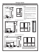
Design Guide (One, Two, or Three Units) Panel Accessories & Dimensions Ǝ FP 6WDLQOHVV 6WHHO 6ROLG 'RRU 3DQHO 2SWLRQV 29-3/4" (75.6 cm) DQG Ǝ FP 7KLFN )UDPH IRU *ODVV 'RRU 29-3/4" (75.6 cm) 23" (58.4 cm) Fresh Food Glass Panel for Fresh Food 45-3/8" (115.3 cm) for 80" (203.2 cm) Installation 49-3/8" (125.4 cm) for 84" (213.4 cm) Installation 6" (15.2 cm) 80" (203.2 cm) Install. 10" (25.4 cm) 84" (213.4 cm) Install. 45-3/8" (115.3 cm) Cabinets 49-3/8" (125.4 cm) 6" (15.
Design Guide (One, Two, or Three Units) 3/4Ǝ FP &86720 3$1(/ ',0(16,216 Ǝ FP +LJK )XOO\ Integrated Installation NOTE: 7KLV SURGXFW LV GHVLJQHG WR KDQGOH Ǝ FP panels that are made of wood. Ǝ [ Ǝ [ FP LV WKH PD[LPXP opening for a glass window. The opening may be smaller if desired. If you choose to install custom panels, they must be cut to the dimensions shown. The panels will attach to the door and drawers using a hook and bracket system.
Installation Instructions INSTALLATION INSTRUCTIONS FOR SINGLE UNIT TOOLS REQUIRED MATERIALS REQUIRED Ǝ $OOHQ ZUHQFK • Utility knife • Stepladder • Bucket • Level • Appliance hand truck • Tubing cutter Ǝ RSHQ HQG ZUHQFK Ǝ RSHQ HQG ZUHQFK • #2 Phillips screwdriver • Drill and bit set Ǝ VRFNHW • Safety glasses • Pliers Ǝ UDWFKHW • Torx T-20, T-30 wrench Ǝ FRSSHU ZDWHU OLQH WXELQJ RU 6PDUW&RQQHFW Refrigerator Tubing kits • Water shut-off valve • Custom panels for refri
Installation Instructions INSTALLATION INSTRUCTIONS FOR SINGLE UNIT STEP 1 REMOVE PACKAGING WARNING Tip Over Hazard. This appliance is top heavy. Use extreme caution with moving to prevent tipping over which could result in death or serious injury. Ŷ Cut bands and tape on the top and bottom of packaging with a utility knife. Ŷ Unfold the cardboard seams and remove the top of the packaging. Ŷ Slide the remainder of the box off of the appliance.
Installation Instructions INSTALLATION INSTRUCTIONS FOR SINGLE UNIT (cont.) WARNING STEP 3 CONNECT WATER LINE Tip Over Hazard. These appliances are top heavy, especially with any doors open, and must be secured to prevent tipping forward which could result in death or serious injury. Read and follow the entire installation instructions for securing the appliance with the anti-tip system.
Installation Instructions INSTALLATION INSTRUCTIONS FOR SINGLE UNIT (cont.) STEP 5 SLIDE UNIT INTO ENCLOSURE STEP 6 REMOVE TOEKICK AND VENT Roll the unit into the enclosure, being careful not to pinch the water line or power cord. The toekick must be removed to access the leveling leg system. Ŷ Remove band around EPS block in front of toekick. Ŷ Remove and dispose of EPS block. Ŷ Remove the solid portion of the toekick by pulling forward.
Installation Instructions INSTALLATION INSTRUCTIONS FOR SINGLE UNIT (cont.) STEP 8 INSTALL TOEKICK AND VENT STEP 9 REVERSE DOOR SWING (if needed) (cont.) 8VLQJ D Ǝ $OOHQ ZUHQFK UHPRYH WKH VFUHZV per hinge that secure the door to the unit. Have someone hold the door while removing these screws to keep the door from falling. Ŷ Locate the toekick, vent and screws (removed earlier). Ŷ A custom toekick can be installed to match or complement the surrounding cabinetry.
Installation Instructions INSTALLATION INSTRUCTIONS FOR SINGLE UNIT (cont.) STEP 9 REVERSE DOOR SWING (cont). STEP 10 ADJUST DOOR SWING (if needed) 10. To install the top hinge, turn the hinge in the proper direction—the section of the bracket that will be attached to the door should be at the bottom of the hinge. Slide the hinge over the screws and seat the tabs into the hinge pocket. Tighten the screws. NOTE: This unit has a 2-position door stop.
Installation Instructions INSTALLATION INSTRUCTIONS FOR SINGLE UNIT (cont.) STEP 12 INSTALL DOOR AND DRAWER PANELS 5. Open the refrigerator door to attach the refrigerator panel. 6. Rest the refrigerator panel on the refrigerator door by aligning the hooks on the panel brackets with the adjustment pins on the door. 1. Remove all door and drawer panel hardware and trim from the unit.
Installation Instructions INSTALLATION INSTRUCTIONS FOR SINGLE UNIT (cont.) STEP 12 INSTALL DOOR AND DRAWER PANELS (cont.) STEP 13 START ICEMAKER Ŷ Press the zone indicator on the control pad twice to select the freezer drawer. Press the ICE icon on the right side of the control. A line will appear under ICE to show that the icemaker is ON. Ŷ Be sure nothing interferes with the sweep of the feeler arm. Ŷ Discard the first full bucket of ice cubes. 10. Repeat steps 5-9 for the freezer drawer. 11.
Installation Instructions INSTALLATION INSTRUCTIONS FOR MULTIPLE UNITS TOOLS REQUIRED • Drywall Anchors and screws Ǝ $OOHQ ZUHQFK • Utility knife • Stepladder • Bucket • Level • Appliance hand truck • Tubing cutter Ǝ RSHQ HQG ZUHQFK Ǝ RSHQ HQG ZUHQFK • #2 Phillips screwdriver • Drill and bit set Ǝ VRFNHW • Safety glasses • Pliers Ǝ UDWFKHW • Torx T-20, T-30 wrench MATERIALS REQUIRED PER UNIT HARDWARE SUPPLIED PER UNIT Ǝ FRSSHU ZDWHU OLQH WXELQJ RU 6PDUW&RQQHFW Ref
Installation Instructions INSTALLATION INSTRUCTIONS FOR MULTIPLE UNITS (cont.) 67(3 5(029( 3$&.$*,1* $// 81,76 WARNING Tip Over Hazard. This appliance is top heavy. Use extreme caution with moving to prevent tipping over which could result in death or serious injury. Ŷ Cut bands and tape on the top and bottom of packaging with a utility knife. Ŷ Unfold the cardboard seams and remove the top of the packaging. Ŷ Slide the remainder of the box off of the appliance.
Installation Instructions INSTALLATION INSTRUCTIONS FOR MULTIPLE UNITS (cont.) STEP 2 INSTALL HEATER UNIFICATION KIT(S) TO UNIT 2 WARNING Ŷ Remove paper backing from heater and carefully apply heater to LEFT side of unit 2. Apply heater 3/8” (1 cm) from the front edge and 4” (10 cm) from the top edge. NOTE: Heater is always applied on the left side (when facing the front) of the unit. Heater may cover the lower portion of the warning label. Ŷ Secure the heater harness with tape as shown. Tip Over Hazard.
Installation Instructions INSTALLATION INSTRUCTIONS FOR MULTIPLE UNITS (cont.) STEP 2 INSTALL HEATER UNIFICATION KIT(S) TO UNIT 2 (cont.) Ŷ Attach joining bracket to unit 2 using screws from the kit. Ŷ Attach joining bracket to unit 1 using screws from Heater Unification Kit. Joining Bracket Ŷ Attach trim cover holder clips to the left side of unit 1, 4mm from the front edge. Clip 1 should line up with the hole at the upper left corner. Clip 4 should line up just below the top door.
Installation Instructions INSTALLATION INSTRUCTIONS FOR MULTIPLE UNITS (cont.) STEP 2 INSTALL HEATER UNIFICATION KIT(S) TO UNIT 2 (cont.) STEP 3 REVERSE DOOR SWING (UNIT 1) Ŷ Remove the top and bottom trim covers from unit 1. Top Trim Cover Ŷ Move the two (or more) units together and align the front. Ŷ Attach units 1 and 2 at the back using screws and nuts from the =8* +HDWHU 8QL¿FDWLRQ NLW -RLQ DQ\ remaining units in the same way.
Installation Instructions INSTALLATION INSTRUCTIONS FOR MULTIPLE UNITS (cont.) STEP 3 REVERSE DOOR SWING (UNIT 1) (Cont.) 8VLQJ D Ǝ $OOHQ ZUHQFK UHPRYH WKH VFUHZV SHU hinge that secure the door to the unit. Have someone hold the door while removing these screws to keep the door from falling. 9. Install the screws on the refrigerator compartment cabinet in all 4 places. Screw them in about halfway.
Installation Instructions INSTALLATION INSTRUCTIONS FOR MULTIPLE UNITS (cont.) STEP 4 ADJUST DOOR SWING (if needed) STEP 5 INSTALL DOOR BRACKET COVERS (UNIT 1) NOTE: This unit has a 2-position door stop. When space does not allow the door to swing to 115°, you may limit the door swing to 90°. A 90° setting is recommended for any installation where a unit has another unit on both sides. Skip this step if door opening is satisfactory for your installation situation.
Installation Instructions INSTALLATION INSTRUCTIONS FOR MULTIPLE UNITS (cont.) 67(3 ,167$// $17, 7,3 BRACKETS STEP 9 CONNECT WATER LINE Ŷ Locate Anti-tip brackets for all units. Ŷ ,QVLGH WRS IDFH RI EUDFNHW VKRXOG EH LQVWDOOHG DW Ǝ FP ³6ORWƎ LQ EUDFNHW VKRXOG WR EH SODFHG LQ FHQWHU RI LQVWDOO VSDFH W\SLFDOO\ Ǝ > FP@ IURP the outside). Ŷ Mark (within slots, placement) stud and anchor positions on brackets. Ŷ Secure brackets using a combination of studs & anchors.
Installation Instructions INSTALLATION INSTRUCTIONS FOR MULTIPLE UNITS (cont.) STEP 11 SLIDE UNITS INTO ENCLOSURES STEP 12 INSTALL HINGE GUARD Ŷ Locate panel attachment set in the bottom drawer. Ŷ 8VLQJ VFUHZV SURYLGHG DWWDFK KLQJH JXDUGV WR WKH upper and lower hinge side of the door. Ŷ Roll the units into the enclosure, being careful not to pinch the water lines or power cords. Hinge Guard Make sure side heater connection is accessible between units.
Installation Instructions INSTALLATION INSTRUCTIONS FOR MULTIPLE UNITS (cont.) STEP 13 CONNECT HEATER (Cont.) STEP 14 LEVEL UNITS Ŷ ,QVWDOO +HDWHU :LUH 6WUDLQ 5HOLHI LQ *ULOOH 6ORW. All models have 4-point leveling. The front is supported E\ OHYHOLQJ OHJV WKH UHDU LV VXSSRUWHG E\ DGMXVWDEOH wheels. Both are accessible from the front of the unit. Ŷ 7R OHYHO WKH EDFN RI WKH XQLW WXUQ WKH Ǝ KH[ nut located above the front wheels. Turn counter clockwise to raise or clockwise to lower the unit.
Installation Instructions INSTALLATION INSTRUCTIONS FOR MULTIPLE UNITS (cont.) STEP 15 INSTALL TOEKICK AND VENT STEP 16 INSTALL FRONT TRIM Attach front trim piece, provided in the Heater Unification Kit, along length of units from top to bottom by snapping into the clips that were attached in step 2. Ŷ Locate the toekick, vent and screws (removed earlier). Ŷ A custom toekick can be installed to match or complement the surrounding cabinetry. Use the supplied toekick as a template.
Installation Instructions INSTALLATION INSTRUCTIONS FOR MULTIPLE UNITS (cont.) STEP 17 INSTALL DOOR AND DRAWER PANELS 5. Open the refrigerator door to attach the refrigerator panel. 6. Rest the refrigerator panel on the refrigerator door by aligning the hooks on the panel brackets with the adjustment pins on the door. 1. Remove all door and drawer panel hardware and trim from the unit.
Installation Instructions INSTALLATION INSTRUCTIONS FOR MULTIPLE UNITS (cont.) STEP 17 INSTALL DOOR AND DRAWER PANELS (cont.) STEP 18 START ICEMAKER Ŷ Press the zone indicator on the control pad twice to select the freezer drawer. Press the ICE icon on the right side of the control. A line will appear under ICE to show that the icemaker is ON. Ŷ Be sure nothing interferes with the sweep of the feeler arm. Ŷ Discard the first full bucket of ice cubes. 10. Repeat steps 5-9 for the freezer drawer. 11.
Notes
NOTE: While performing installations described in this book, safety glasses or goggles should be worn. NOTE: Product improvement is a continuing endeavor at Monogram. Therefore, materials, appearance and specifications are subject to change without notice. 31-1000169 Rev.
INSTRUCTIONS D’INSTALLATION Réfrigérateur encastré de 30 po à congélateur en bas Réserve de vin encastrée de 30 po à congélateur en bas FRANÇAIS MONOGRAM.
Consignes de Sécurité AVANT DE COMMENCER Veuillez lire toutes ces instructions attentivement. • Niveau de compétence – L’installation de cet appareil exige des compétences de base en mécanique, menuiserie et plomberie. La responsabilité d’une installation adéquate relève de l’installateur. La garantie Monogram ne couvre pas les défectuosités du produit causées par une installation inadéquate. Consultez le manuel d’utilisation pour des renseignements sur la garantie.
Safety Information AVERTISSEMENT RISQUE D’EXPLOSION Fluide frigorigène inflammable Cet électroménager contient le réfrigérant isobutane, R600a, un gaz naturel à compatibilité élevée avec l’environnement. Il s’agit cependant d’un combustible. Observez les consignes de sécurité ci-dessous afin de réduire le risque de blessure ou de dommage à la propriété.
Guide de conception (une unité) Dimensions de l’enceinte pour instructions relatives à un encastrement complet Profondeur minimum de 64 cm (25 po) Largeur hors-tout de 76 cm (30 po) Options de hauteur de 203 ou 213 cm (80 ou 84 po) L’ouverture découpée doit avoir une profondeur minimale de 25 po pour un montage sans renfoncement. • La face avant du réfrigérateur doit être au même niveau que les meubles adjacents avec une profondeur de 25 po.
Guide de conception Dimensions de l’unité avec panneaux 3/4 po Cuve Dessus avec panneaux Porte 23-3/4" (Cuve et porte seulement) (60.3 cm) 3/4" (19.1 mm) Panneau 29-3/4" (75.6 cm) Hauteuradjustable ajustable Height de 79 3/8” à 80 3/8” * from (201,6 cmto- 80-3/8” 204,2 cm)* 79-3/8” 1/8" (3.2 mm) Dégagement (201.6 cm - 204.2 cm) 6" (15.2 cm) 4" (10.2 cm) 1-1/4" (3.
Guide de conception Dimensions de l’enceinte pour unité simple ou unités multiples INSTALLATION D’UN SEUL PRODUIT Emplacement de la patte antibasculement - N’obstruez PAS cette zone. REMARQUES : • Lorsque deux ou trois unités sont installées côte j F{WH XQ pOpPHQW FKDXႇDQW H[WpULHXU GRLW rWUH posé sur la paroi extérieure gauche de la deuxième ou troisième unité. Voir la trousse d’union SRXU pOpPHQW FKDXႇDQW H[WpULHXU 30” (76.2 cm) Côté charnière 77” (195.5 cm) Hauteur de l’ouverture 80” (203.
Guide de conception (Une, deux ou trois unités) THE INSTALLATION SPACE (Per Unit) Water and Electrical Locations Repérez les connexions de l’alimentation électrique et d’eau dans les zones illustrées sur la page des dimensions d’enceinte. AVERTISSEMENT Raccordez l’appareil à une alimentation d’eau potable seulement. PRÉPARATION DEL’INSTALLATION DU TUYAU D’EAU • Une alimentation d’eau froide est requise pour faire fonctionner la machine à glaçons automatique.
Guide de conception (Une, deux ou trois unités) Acier inoxydable ou sur mesure Coupe horizontale OUVERTURE DE PORTE À 115°(réglage d’usine) Allouez un dégagement Allow 17" minimum minimal de(43.2 17 pocm) (43,2 cm) à clearance to a wall for a fullde un mur pour une ouverture 115° door swing. porte complète à 115°. Refrigerator 1/8" (3.2 mm) 1-3/8" (3.5 cm) 2-1/16" (5.4 cm) 3/4" (1.9 cm) 1" 1-1/4" 1-1/2" (3.2 cm) (2.5 cm) (3.8 cm) 3/4" (1.9 cm) 1" (2.5 cm) 1-1/4" (3.2 cm) 1-1/2" (3.
Guide de conception (Une, deux ou trois unités) Acier inoxydable ou sur mesure Coupe horizontale OUVERTURE DE PORTE À 90°(réglages en option) Pour ouverture de For une a 90º door swing porte à 90º, allouez un allow 4" (10.2 cm) dégagement minimal min. clearance to a de 4 po (10,2 cm) wall, for stainless jusqu’au mur s’il s’agit steel models. d’un modèle en acier inoxydable. Refrigerator 1/8" (3.2 mm) 3/4" 1" 2-1/4" 1-1/4" (2.5 cm) (1.9 cm) 1-3/16" (5.7 cm) 1-1/2" (3 cm) (3.8 cm) (3.2 cm) 3/4" (1.
Guide de conception (Une, deux ou trois unités) Accessoires et dimensions des panneaux 29-3/4" (75.6 cm) Options de panneau de porte solide en acier inoxydable de 3/4 po (1,9 cm) — Cadre épais pour porte en verre 29-3/4" (75.6 cm) 23" (58.4 cm) Glass Panel for Fresh Food Réfrigérateur Fresh Food 4545-3/8" 3/8” (115,3 cm) (115.3 cm) for pour installation 80” 80" (203.2 cm) Installation 49-3/8"cm), (125.449 cm) for (203,2 3/8” 84" (213.
Guide de conception (Une, deux ou trois unités) DIMENSIONS D’UN PANNEAU SUR MESURE DE 3/4 po Installation totalement encastrée de 80 po de hauteur En cas d’installation de panneaux sur mesure, ceux-ci doivent être coupés aux dimensions indiquées. Les panneaux se fixeront à la porte et aux tiroirs à l’aide d’un système de crochets et de pattes.
Instructions d’installation INSTRUCTIONS D’INSTALLATION POUR UNITÉ SIMPLE OUTILS REQUIS ÉQUIPEMENT REQUIS • • • • • Clé Allen de 5/32 po Couteau à lame rétractable Escabeau Seau Niveau • • • • • • • • • • • Diable pour électroménagers Coupe-tuyau Clé ouverte 7/16 po Clé ouverte 1 5/16 po Tournevis Phillips cruciforme #2 Perceuse et jeu de forets Douille 5/16 po Lunettes de sécurité Pinces Cliquet 3/8 po Torx T-20, T-30 clé • Tuyau d’alimentation d’eau en cuivre d’ ¼ po ou trousse pour réfrigérateur Sm
Instructions d’installation INSTRUCTIONS D’INSTALLATION POUR UNITÉ SIMPLE (suite) ÉTAPE 1 RETRAIT DE L’EMBALLAGE AVERTISSEMENT Risque de basculement. Cet électroménager est lourd du haut. Usez d’extrême prudence en le déplaçant afin de prévenir un basculement susceptible d’occasionner des blessures graves ou la mort. Ŷ Coupez les courroies et le ruban adhésif sur le haut et sur le bas de l’emballage à l’aide d’un couteau à lame rétractable.
Instructions d’installation INSTRUCTIONS D’INSTALLATION POUR UNITÉ SIMPLE (suite) AVERTISSEMENT ÉTAPE 3 CONNECT CONDUITE D’EAU Risque de basculement. Ces électroménagers sont lourds du haut, notamment lorsqu’une porte est ouverte, de sorte qu’ils doivent être fixés pour prévenir un basculement vers l’avant susceptible d’occasionner des blessures graves ou la mort.
Instructions d’installation INSTRUCTIONS D’INSTALLATION POUR UNITÉ SIMPLE (suite) ÉTAPE 6 INSTALLATION DE LA PLINTHE ET DE L’ÉVENT ÉTAPE 5 POSITIONNEMENT DE L’APPAREIL DANS SON ENCEINTE La plinthe doit être enlevé pour accéder à la legstyle nivellement Faites rouler l’appareil dans son enceinte, en s’assurant de ne pas accrocher le tuyau d’eau ou le câble d’alimentation. Ŷ Retirez la partie pleine de la plinthe en la tirant vers l’avant.
Instructions d’installation INSTRUCTIONS D’INSTALLATION POUR UNITÉ SIMPLE (suite) ÉTAPE 8 INVERSION DE L’OUVERTURE DE PORTE ÉTAPE 9 INVERSION DE L’OUVERTURE DE PORTE (si nécessaire) (suite) Ŷ Localisez la plinthe, l’évent et les vis (retirés précédemment). 3. A l’aide d’une clé hexagonale de type Allen de 5/32 po, retirez les deux vis de chaque charnière qui maintiennent la porte sur le réfrigérateur.
Instructions d’installation INSTRUCTIONS D’INSTALLATION POUR UNITÉ SIMPLE (suite) ÉTAPE 10 RÉGLAGE DE L’OUVERTURE DE PORTE (si nécessaire) ÉTAPE 9 INVERSION DE L’OUVERTURE DE PORTE (si nécessaire) (suite) 10. Pour installer la charnière supérieure, placez la charnière dans le bon sens - la partie du support qui sera fixée à la porte doit être sur le bas de la charnière. Faites glisser la charnière sur les vis et placez les languettes dans le compartiment de la charnière. Serrez les vis.
Instructions d’installation INSTRUCTIONS D’INSTALLATION POUR UNITÉ SIMPLE (suite) ÉTAPE 12 INSTALLATION DES PANNEAUX DE PORTE ET TIROIR 1. Retirez toute la quincaillerie de porte et de tiroir et la garniture du réfrigérateur. Article Quantité Supports du panneau 12 Vis de mécanique à tête cruciforme (pour panneau en acier inoxydable) 34 Vis à tête six-pans 12 Rondelles 12 Garniture de porte 6 Capuchons pour garniture 12 Clé hexagonale 2 2.
Instructions d’installation INSTRUCTIONS D’INSTALLATION POUR UNITÉ SIMPLE (suite) ÉTAPE 12 INSTALLATION DES PANNEAUX DE PROTE ET DE TIROIR (suite) ÉTAPE 13 MISE EN MARCHE DE LA MACHINE À GLAÇONS Ŷ Appuyez deux fois sur le voyant ZONE sur le panneau de commande pour sélectionner le tiroir congélateur. Appuyez sur l’icône ICE (glaçon) sur le côté droit des commandes. Une ligne apparaitra sous ICE (Glaçon) pour indiquer que la machine à glaçons est activée.
Instructions d’installation INSTRUCTIONS D’INSTALLATION POUR UNITÉS MULTIPLES OUTILS REQUIS ÉQUIPEMENT REQUIS • • • • • Clé Allen de 5/32 po Couteau à lame rétractable Escabeau Seau Niveau • • • • • • • • • • • Diable pour électroménagers Coupe-tuyau Clé ouverte 7/16 po Clé ouverte 1 5/16 po Tournevis Phillips cruciforme #2 Perceuse et jeu de forets Douille 5/16 po Lunettes de sécurité Pinces Cliquet 3/8 po Torx T-20, T-30 clé • Tuyau d’alimentation d’eau en cuivre d’ ¼ po ou trousse pour réfrigérateu
Instructions d’installation INSTRUCTIONS D’INSTALLATION POUR UNITÉS MULTIPLES (suite) ÉTAPE 1 RETRAIT DE L’EMBALLAGE AVERTISSEMENT Risque de basculement. Cet électroménager est lourd du haut. Usez d’extrême prudence en le déplaçant afin de prévenir un basculement susceptible d’occasionner des blessures graves ou la mort. Ŷ Coupez les courroies et le ruban adhésif sur le haut et sur le bas de l’emballage à l’aide d’un couteau à lame rétractable.
Instructions d’installation INSTRUCTIONS D’INSTALLATION POUR UNITÉS MULTIPLES (suite) ÉTAPE 2 INSTALLER LA/LES TROUSSE(S) D’UNION POUR ÉLÉMENT CHAUFFANT SUR L’UNITÉ 2 AVERTISSEMENT Risque de basculement. Ces électroménagers sont lourds du haut, notamment lorsqu’une porte est ouverte, de sorte qu’ils doivent être fixés pour prévenir un basculement vers l’avant susceptible d’occasionner des blessures graves ou la mort.
Instructions d’installation INSTRUCTIONS D’INSTALLATION POUR UNITÉS MULTIPLES (suite) ÉTAPE 2 INSTALLER LA/LES TROUSSE(S) D’UNION POUR ÉLÉMENT CHAUFFANT SUR L’UNITÉ 2 (suite) Ŷ )L[H] OH VXSSRUW GH OLDLVRQ VXU O¶XQLWp j O¶DLGH GHV YLV GH OD trousse. Ŷ )L[H] OH VXSSRUW GH OLDLVRQ VXU O¶XQLWp j O¶DLGH GHV YLV GH OD trousse d’union pour élément chauffant. Support de liaison Ŷ Posez les attaches du couvercle de garniture sur le côté gauche de l’unité 1, à 4 mm du bord avant.
Instructions d’installation INSTRUCTIONS D’INSTALLATION POUR UNITÉS MULTIPLES (suite) ÉTAPE 2 INSTALLER LA/LES TROUSSE(S) D’UNION POUR ÉLÉMENT CHAUFFANT SUR L’UNITÉ 2 (suite) ÉTAPE 3 INVERSION DE L’OUVERTURE DE PORTE (UNITÉ 1) Ŷ Retirez les couvercles de garniture supérieur et inférieur de l’unité 1. Couvercle de garniture supérieur Ŷ Déplacez les deux (ou plus) unités ensemble et alignez leur devant.
Instructions d’installation INSTRUCTIONS D’INSTALLATION POUR UNITÉS MULTIPLES (suite) ÉTAPE 3 INVERSION DE L’OUVERTURE DE PORTE (UNITÉ 1) (suite) 3. A l’aide d’une clé hexagonale de type Allen de 5/32 po, retirez les deux vis de chaque charnière qui maintiennent la porte sur le réfrigérateur. Demandez à quelqu’un de tenir la porte pendant que vous retirez ces vis pour éviter que la porte ne tombe. Fentes pour les languettes Vis 10.
Instructions d’installation INSTRUCTIONS D’INSTALLATION POUR UNITÉS MULTIPLES (suite) ÉTAPE 4 RÉGLAGE DE L’OUVERTURE DE PORTE ÉTAPE 5 INSTALLATION DES COUVERCLES DE SUPPORT DE PORTE (UNITÉ 1) (si nécessaire) Installez les couvercles pour dissimuler les supports près des charnières dans le haut et le bas de la porte. Les couvercles s’encliquètent en place. REMARQUE: Ce l’appareil possède 2 butées de position d’ouverture.
Instructions d’installation INSTRUCTIONS D’INSTALLATION POUR UNITÉS MULTIPLES (suite) ÉTAPE 8 INSTALLATION DE LA PATTE ANTI-BASCULEMENT ÉTAPE 9 CONNECT CONDUITE D’EAU Ŷ Repérez les pattes antibasculement de toutes les unités. Ŷ La partie supérieure interne de la patte anti-basculement doit être installée à une hauteur de 80 po (203.2 cm). La « fente » dans la patte doit être placée au centre de l’espace d’installation (généralement à 15 po [38,1 cm] de l’extérieur).
Instructions d’installation INSTRUCTIONS D’INSTALLATION POUR UNITÉS MULTIPLES (suite) ÉTAPE 11 GLISSER LES UNITÉS DANS LES ENCEINTES ÉTAPE 12 INSTALLER LE COUVERCLE DE CHARNIÈRE Ŷ Faites rouler l’appareil dans son enceinte, en s’assurant de ne pas accrocher le tuyau d’eau ou le câble d’alimentation. Ŷ 5HSpUH] O¶HQVHPEOH GH IL[DWLRQ GH SDQQHDX GDQV OH WLURLU GX bas. Ŷ ¬ O¶DLGH GHV YLV IRXUQLHV IL[H] OHV FRXYHUFOHV GH FKDUQLqUH sur le côté charnière supérieur et inférieur de la porte.
Instructions d’installation INSTRUCTIONS D’INSTALLATION POUR UNITÉS MULTIPLES (suite) ÉTAPE 13 CONNECTER L’ÉLÉMENT CHAUFFANT (suite) ÉTAPE 14 MISE À NIVEAU DE L’UNITÉ Ŷ Installez le serre-câble de l’élément chauffant dans la fente de la grille. Ŷ ,QVWDOOH] OH WUDQVIRUPDWHXU VXU OD SDURL PXU j OD JDXFKH GH OD tuyauterie de cuivre. transformateur Tous les modèles possèdent quatre points de mise à niveau. L’avant est soutenu par des pieds de mise à niveau, l’arrière par des roulettes réglables.
Instructions d’installation INSTRUCTIONS D’INSTALLATION POUR UNITÉS MULTIPLES (suite) ÉTAPE 15 INVERSION DE L’OUVERTURE DE PORTE ÉTAPE 16 INSTALLER LA GARNITURE FRONTALE Ŷ Localisez la plinthe, l’évent et les vis (retirés précédemment). Fixez la pièce de garniture frontale (fournie dans la trousse d’union pour élément chauffant) le long des unités de haut en bas en l’enclenchant dans les attaches fixées à l’étape 2.
Instructions d’installation INSTRUCTIONS D’INSTALLATION POUR UNITÉS MULTIPLES (suite) ÉTAPE 17 INSTALLATION DES PANNEAUX DE PORTE ET TIROIR 1. Retirez toute la quincaillerie de porte et de tiroir et la garniture du réfrigérateur. Article Quantité Supports du panneau 12 Vis de mécanique à tête cruciforme (pour panneau en acier inoxydable) 34 Vis à tête six-pans 12 Rondelles 12 Garniture de porte 6 Capuchons pour garniture 12 Clé hexagonale 2 2.
Instructions d’installation INSTRUCTIONS D’INSTALLATION POUR UNITÉS MULTIPLES (suite) ÉTAPE 17 INSTALLATION DES PANNEAUX DE PROTE ET DE TIROIR (suite) ÉTAPE 18 MISE EN MARCHE DE LA MACHINE À GLAÇONS Ŷ Appuyez deux fois sur le voyant ZONE sur le panneau de commande pour sélectionner le tiroir congélateur. Appuyez sur l’icône ICE (glaçon) sur le côté droit des commandes. Une ligne apparaitra sous ICE (Glaçon) pour indiquer que la machine à glaçons est activée.
Notes
REMARQUE : Des lunettes de protection doivent être portées lors de la réalisation des installations décrites dans ce manuel. REMARQUE : L’amélioration des produits fait l’objet d’un effort constant chez Monogram. Par conséquent, le matériel, l’aspect et les caractéristiques des produits sont susceptibles d’être modifiés sans préavis. 31-1000169 Rev.
INSTRUCCIONES DE INSTALACIÓN Refrigerador con Freezer Inferior Integrado de 30” Cava de Vinos con Freezer Inferior Integrado de 30” ESPAÑOL. MONOGRAM.
Información sobre Seguridad ANTES DE COMENZAR Si la unidad que recibió está dañada, se deberá comunicar de inmediato con su vendedor o fabricante. Lea estas instrucciones en su totalidad y atentamente. • • • IMPORTANTE – Conserve estas instrucciones para uso del inspector local. Cumpla con todos los códigos y ordenanzas gubernamentales. Nota para el Instalador – Asegúrese de que el Comprador conserve estas instrucciones.
Información sobre seguridad ADVERTENCIA PELIGRO DE EXPLOSIÓN Refrigerantes Inflamables Este electrodoméstico cuenta con refrigerante isobutano, R600a, un gas natural con alto nivel de compatibilidad medioambiental. Sin embargo, también es combustible. Siga las advertencias que figuran a continuación, a fin de reducir el riesgo de lesiones o daños sobre la propiedad. 1) Al mover, instalar y operar el electrodoméstico, se deberá tener cuidado de no dañar la tubería del refrigerante.
Guía de Diseño (Una Unidad) Dimensiones del Espacio de Protección del Gabinete para Instrucciones Completamente Integradas Profundidad min. de 25" (63.5 cm) Ancho Final de 30" (76.2 cm) Opciones de altura de 80" (203.2 cm) o *84" (213.4 cm) La profundidad del disyuntor deberá VHU GH Ǝ SDUD LQVWDODFLRQHV DO mismo nivel. • La cara frontal del refrigerador se encuentra al mismo nivel que los JDELQHWHV DG\DFHQWHV GH Ǝ cm) de profundidad.
Guía de Diseño (Una Unidad) 'LPHQVLRQHV GHO 5HIULJHUDGRU FRQ 3DQHOHV GH Ǝ Cubierta Parte Superior con Paneles Puerta 23-3/4" (Case and Door only) (60.3 cm) 3/4" (19.1 mm) Panel 29-3/4" (75.6 cm) Height adjustable Altura ajustable from des GH Ǝ KDVWD Ǝ 79-3/8” to 80-3/8” * (201.6 cm - 204.2 cm) (201.6 cm - 204.2 cm) 1/8" (3.2 mm) Espacio Libre 6" (15.2 cm) 4" (10.2 cm) 1-1/4" (3.
Guía de Diseño Dimensiones del Espacio de Protección para Unidades Individuales y Múltiples INSTALACIÓN DE UN PRODUCTO NOTAS: • Cuando dos o más unidades sean instaladas una al lado de la otra, se deberá aplicar un calefactor exterior a la pared exterior izquierda de la segunda y/o tercera unidad. Consulte el .LW GH 8QL¿FDFLyQ GHO &DOHIDFWRU ([WHULRU Ubicación del Soporte Antivolcaduras – NO obstruya esta área. 30” (76.2 cm) 1 por producto 77” (195.5 cm) Altura de Apertura 80” (203.2 cm) min.
Guía de Diseño (Una, Dos o Tres Unidades) EL ESPACIO DE INSTALACIÓN (Por Unidad) Ubicaciones de Agua y Electricidad Ubique las conexiones eléctricas y de suministro de agua en las áreas que se muestran en la página de la sección de Dimensiones de Gabinetes. ADVERTENCIA Realice la conexión a un suministro de agua potable únicamente. PREPARACIÓN PARA INSTALAR EL SUMINISTRO DE AGUA • Se requiere un suministro de agua fría para el funcionamiento de la máquina de hielo automática.
Guía de Diseño (Una, Dos o Tres Unidades) Vista Superior de los Paneles Acero Inoxidable o A Medida GIRO DE PUERTA DE 115º (original de fábrica) Refrigerator Cuente con(43.2 un espacio libre Allow 17" cm) minimum mínimo de 17” (43.2 cm) hasta clearance to a wall for a full una pared para un balanceo de 115° door swing. puerta completo de 115°. 1/8" (3.2 mm) 1-3/8" (3.5 cm) 2-1/16" (5.4 cm) 3/4" (1.9 cm) 1" 1-1/4" 1-1/2" (3.2 cm) (2.5 cm) (3.8 cm) 3/4" (1.9 cm) 1" (2.5 cm) 1-1/4" (3.2 cm) 1-1/2" (3.
Guía de Diseño (Una, Dos o Tres Unidades) Acier inoxydable ou sur mesure Coupe horizontale OUVERTURE DE PORTE À 90°(réglages en option) Con los modelos de acero Forinoxidable, a 90º doorpara swing un giro allowde4"puerta (10.2 de cm)90° dejemin. un espacio libre clearance to a mínimo (10.2 cm) wall, de for4” stainless consteel relación a la pared. models. Refrigerator 1/8" (3.2 mm) 3/4" 1" 2-1/4" 1-1/4" (2.5 cm) (1.9 cm) 1-3/16" (5.7 cm) 1-1/2" (3 cm) (3.8 cm) (3.2 cm) 3/4" (1.9 cm) Top hinge 1" (2.
Guía de Diseño (Una, Dos o Tres Unidades) Accesorios y Dimensiones del Panel 29-3/4" (75.6 cm) Ǝ FP ± 2SFLRQHV GHO 3DQHO GH 3XHUWD GH $FHUR ,QR[LGDEOH 6yOLGR GH Ǝ FP 0DUFR *UXHVR SDUD Puerta de Vidrio 23" (58.4 cm) 29-3/4" (75.6 cm) Glass Panel for Fresh Food Comida Fresh Fresca Food 45 3/8” (115.3 cm) para 45-3/8" (115.3 Instalación de 80” (203.2 80" (203.2 cm) 49 3/8” (125.4 (125.4 cm) para 49-3/8" 84" (213.4 cm) de 84” (213.4 Instalación 6" (15.2 cm) 80" (203.2 cm) Install.
Guía de Diseño (Una, Dos o Tres Unidades) ',0(16,21(6 '(/ 3$1(/ $ 0(','$ '( Ǝ FP ,QVWDODFLyQ 7RWDOPHQWH ,QWHJUDGD D una Altura de Ǝ FP Si decide instalar paneles a medida, se deberán cortar en las dimensiones que se muestran. Los paneles serán añadidos a la puerta y cajones, usando un sistema de ganchos y soportes.
Instrucciones de Instalación INSTRUCCIONES DE INSTALACIÓN PARA LA UNIDAD INDIVIDUAL HERRAMIENTAS REQUERIDAS MATERIALES REQUERIDOS /ODYH $OOHQ GH Ǝ • Cuchillo multiuso • Escalera de dos hojas • Balde • Nivel • Carro manual para electrodomésticos • Cortador de tubos • Llave de tuercas de 7/16” • Llave de tuercas de 1 5/14” • Destornillador Phillips nº2 • Kit de taladro y broca (QFKXIH GH Ǝ • Gafas de seguridad • Pinzas 7ULQTXHWH GH Ǝ • Torx T-20, T-30 Llave 7XEHUtD GH VXPLQLVWUR GH DJXD G
Instrucciones de Instalación INSTRUCCIONES DE INSTALACIÓN PARA LA UNIDAD INDIVIDUAL (cont.) PASO 1 RETIRE EL EMBALAJE ADVERTENCIA Riesgo de Caída. Este electrodoméstico es inestable. Tenga extremo cuidado al mover lo, a fin de evitar caídas hacia adelante que podrían resultar en la muerte o lesiones graves. Ŷ Recorte las bandas y cintas de la parte superior e inferior del embalaje con un cuchillo multiuso. Ŷ 'HVSOLHJXH ODV MXQWDV GHO FDUWyQ \ UHWLUH OD SDUWH VXSHULRU GHO embalaje.
Instrucciones de Instalación INSTRUCCIONES DE INSTALACIÓN PARA LA UNIDAD INDIVIDUAL (cont.) ADVERTENCIA PASO 3 CONECTAR LA LÍNEA DE AGUA Riesgo de Caídas . Estos electrodomésticos son inestables, especialmente cuando una puerta se encuentre abierta, y deben estar asegurados a fin de evitar caídas hacia adelante que podrían resultar en la muerte o en lesiones graves. Lea y siga las instrucciones de instalación en su totalidad para asegurar el electrodoméstico con el sistema antivolcaduras.
Instrucciones de Instalación INSTRUCCIONES DE INSTALACIÓN PARA LA UNIDAD INDIVIDUAL (cont.) PASO 5 DESLICE LA UNIDAD HASTA EL ESPACIO DE PROTECCIÓN PASO 6 RETIRE EL TOPE DE PIE Y LA VENTILACIÓN Lleve la unidad hasta el espacio de protección, evitando retorcer la tubería de suministro de agua y el cable de corriente. El zócalo debe ser removido para acceder a la nivelación legstyle Ŷ Retire la parte sólida del tope de pie empujando hacia adelante.
Instrucciones de Instalación INSTRUCCIONES DE INSTALACIÓN PARA LA UNIDAD INDIVIDUAL (cont.) PASO 8 INSTALE EL TOPE DE PIE Y LA VENTILACIÓN PASO 9 GIRO DE PUERTA INVERSO (Si es necesario) (cont.) Ŷ Ubique el tope de pie, la ventilación y los tornillos (retirados anteriormente). 8VDQGR XQD OODYH $OOHQ GH Ǝ UHWLUH ORV WRUQLOORV SRU bisagra que aseguran la puerta al refrigerador.
Instrucciones de Instalación INSTRUCCIONES DE INSTALACIÓN PARA LA UNIDAD INDIVIDUAL (cont.) PASO 9 GIRO DE PUERTA INVERSO PASO 10 AJUSTE EL GIRO DE PUERTA (Si es necesario) (Si es necesario) (cont.) 10. Para instalar la bisagra superior, gire la bisagra en la dirección adecuada – la sección del soporte que será añadido a la puerta se deberá encontrar en la parte inferior de la bisagra. Deslice la bisagra sobre los tornillos y coloque las lengüetas en el brazo de la bisagra. Ajuste los tornillos.
Instrucciones de Instalación INSTRUCCIONES DE INSTALACIÓN PARA LA UNIDAD INDIVIDUAL (cont.) PASO 12 INSTALE LOS PANELES DE LAS PUERTAS Y CAJONES 1. Retire todo el equipamiento de los paneles de la puerta y los cajones y cubierta del refrigerador. Elemento Cantidad Soportes de los paneles 12 Tornillos mecánicos Phillips (para usar con el accesorio de panel) 34 Tornillos de cabeza hueca hexagonal Allen 12 Arandelas 12 Cubierta de la puerta 6 Tapas de la cubierta 12 Llave Allen 2 5.
Instrucciones de Instalación INSTRUCCIONES DE INSTALACIÓN PARA LA UNIDAD INDIVIDUAL (cont.) PASO 13 ENCIENDA LA MÁQUINA DE HACER HIELO PASO 12 INSTALE LOS PANELES DE LAS PUERTAS Y CAJONES (cont.) Ŷ Presione el indicador de ZONE (Zona) en la tecla de control dos veces para seleccionar el cajón del freezer. Presione el ícono ICE (Hielo) en el lado derecho del control.
Instrucciones de Instalación INSTRUCCIONES DE INSTALACIÓN PARA UNIDADES MÚLTIPLES HERRAMIENTAS REQUERIDAS MATERIALES REQUERIDOS /ODYH $OOHQ GH Ǝ • Cuchillo multiuso • Escalera de dos hojas • Balde • Nivel • Carro manual para electrodomésticos • Cortador de tubos • Llave de tuercas de 7/16” • Llave de tuercas de 1 5/14” • Destornillador Phillips nº2 • Kit de taladro y broca (QFKXIH GH Ǝ • Gafas de seguridad • Pinzas 7ULQTXHWH GH Ǝ • Torx T-20, T-30 Llave 7XEHUtD GH VXPLQLVWUR GH DJXD GH
Instrucciones de Instalación INSTRUCCIONES DE INSTALACIÓN PARA UNIDADES MÚLTIPLES (cont.) PASO 1 RETIRE EL EMBALAJE ADVERTENCIA Riesgo de Caída. Este electrodoméstico es inestable. Tenga extremo cuidado al moverlo, a fin de evitar caídas hacia adelante que podrían resultar en la muerte o lesiones graves. Ŷ Recorte las bandas y cintas de la parte superior e inferior del embalaje con un cuchillo multiuso. Ŷ 'HVSOLHJXH ODV MXQWDV GHO FDUWyQ \ UHWLUH OD SDUWH VXSHULRU GHO embalaje.
Instrucciones de Instalación INSTRUCCIONES DE INSTALACIÓN PARA UNIDADES MÚLTIPLES (cont.) PASO 2 INSTALE EL KIT(S) DE UNIFICACIÓN DE CALEFACTOR EN LA UNIDAD 2 Ŷ Retire el papel de respaldo del calefactor y con cuidado ubique el calefactor del lado IZQUIERDO de la unidad 2. Coloque el calefactor a 3/8” (1 cm) del extremo frontal y a 4” (10 cm) del extremo superior. NOTA: El calefactor siempre se coloca del lado izquierdo (mirando hacia adelante) de la unidad.
Instrucciones de Instalación INSTRUCCIONES DE INSTALACIÓN PARA UNIDADES MÚLTIPLES (cont.) PASO 2 INSTALE EL KIT(S) DE UNIFICACIÓN DE CALEFACTOR EN LA UNIDAD 2 (cont.) Ŷ Adhiera el soporte de unión a la unidad 2 usando tornillos del kit. Ŷ $GKLHUD HO VRSRUWH GH XQLyQ D OD XQLGDG XVDQGR WRUQLOORV GHO Kit de Unificación del Calefactor Soporte de Unión Ŷ Adhiera las abrazaderas de suspensión de la tapa del marco sobre el lado izquierdo de la unidad a 1.4mm desde el extremo frontal.
Instrucciones de Instalación INSTRUCCIONES DE INSTALACIÓN PARA UNIDADES MÚLTIPLES (cont.) PASO 2 INSTALE EL KIT(S) DE UNIFICACIÓN DE CALEFACTOR EN LA UNIDAD 2 (cont.) PASO 3 GIRO DE PUERTA INVERSO (UNIDAD 1) Ŷ Retire las tapas del marco superior e inferior de la unidad 1. Ŷ 0XHYD ODV GRV R PiV XQLGDGHV MXQWDV \ DOLQHH HO IUHQWH Ŷ $GKLHUD ODV XQLGDGHV \ D OD SDUWH WUDVHUD XVDQGR tornillos y tuercas del Kit de Unificación del Calefactor ZUG30. Una cualquier unidad restante del mismo modo.
Instrucciones de Instalación INSTRUCCIONES DE INSTALACIÓN PARA UNIDADES MÚLTIPLES (cont.) PASO 3 GIRO DE PUERTA INVERSO (UNIDAD 1) (Cont.) 8VDQGR XQD OODYH $OOHQ GH Ǝ UHWLUH ORV WRUQLOORV SRU bisagra que aseguran la puerta al refrigerador. Pida a otra persona que sostenga la puerta, mientras retira estos tornillos para evitar que la puerta sufra una caída. 10.
Instrucciones de Instalación INSTRUCCIONES DE INSTALACIÓN PARA UNIDADES MÚLTIPLES (cont.) PASO 4 AJUSTE EL GIRO DE PUERTA (UNIDAD 1) PASO 5 INSTALE LAS TAPAS DEL SOPORTE DE LA PUERTA (UNIDAD 1) NOTA: El refrigerador cuenta con una detención de la puerta de 2 posiciones. Cuando el espacio no permita que la puerta gire 115º, podrá limitar el giro de la puerta a 90º. Se recomienda una configuración a 90° para cualquier instalación donde una unidad posea otra unidad a ambos lados.
Instrucciones de Instalación INSTRUCCIONES DE INSTALACIÓN PARA UNIDADES MÚLTIPLES (cont.) PASO 8 ,167$/( (/ 623257( $17, VOLCADURAS PASO 9 CONECTAR LA LÍNEA DE AGUA Ŷ Ubique los soportes antivolcaduras de todas las unidades. Ŷ La Cara Superior Interna del soporte se debería instalar a Ǝ FP /D ³5DQXUD´ GHO VRSRUWH VH GHEHUi FRORFDU en el centro del espacio de instalación (Típicamente a 15” (38.1 cm) desde la parte exterior).
Instrucciones de Instalación INSTRUCCIONES DE INSTALACIÓN PARA UNIDADES MÚLTIPLES (cont.) PASO 11 DESLICE LA UNIDAD HASTA EL ESPACIO DE PROTECCIÓN PASO 12 INSTALE EL PROTECTOR DE LA BISAGRA Ŷ Lleve la unidades hasta el espacio de protección, evitando retorcer la tubería de suministro de agua y el cable de corriente. Ŷ 8ELTXH HO FRQMXQWR GH DGKHVLyQ GHO SDQHO HQ HO FDMyQ inferior.
Instrucciones de Instalación INSTRUCCIONES DE INSTALACIÓN PARA UNIDADES MÚLTIPLES (cont.) PASO 13 CONECTE EL CALEFACTOR (Cont.) PASO 14 NIVELE LA UNIDAD Todos los modelos cuentan con 4 puntos de nivelación. La SDUWH IURQWDO HVWi DSR\DGD VREUH SDWDV QLYHODGRUDV OD SDUWH trasera está apoyada sobre ruedas ajustables. Es posible acceder a ambas desde la parte frontal del refrigerador.
Instrucciones de Instalación INSTRUCCIONES DE INSTALACIÓN PARA UNIDADES MÚLTIPLES (cont.) PASO 15 INSTALE EL TOPE DE PIE Y LA VENTILACIÓN PASO 16 INSTALE EL MARCO FRONTAL Ŷ Ubique el tope de pie, la ventilación y los tornillos (retirados anteriormente). Adhiera la pieza del marco frontal, provista con el kit de Unificación del Calefactor, sobre la longitud de las unidades desde la parte superior a la parte inferior, calzando la misma sobre las abrazaderas que se adhirieron en el paso 2.
Instrucciones de Instalación INSTRUCCIONES DE INSTALACIÓN PARA UNIDADES MÚLTIPLES (cont.) PASO 17 INSTALE LOS PANELES DE LAS PUERTAS Y CAJONES 1. Retire todo el equipamiento de los paneles de la puerta y los cajones y cubierta del refrigerador. Elemento Cantidad Soportes de los paneles 12 Tornillos mecánicos Phillips (para usar con el accesorio de panel) 34 Tornillos de cabeza hueca hexagonal Allen 12 Arandelas 12 Cubierta de la puerta 6 Tapas de la cubierta 12 Llave Allen 2 5.
Instrucciones de Instalación INSTRUCCIONES DE INSTALACIÓN PARA UNIDADES MÚLTIPLES (cont.) PASO 17 INSTALE LOS PANELES DE LAS PUERTAS Y CAJONES (cont.) PASO 18 ENCIENDA LA MÁQUINA DE HACER HIELO 10. Repita los pasos 5-9 para el cajón del freezer. 11. Repita los pasos 5-9 para el cajón adaptable. 12. Ajuste todos los tornillos cuando haya comprobado la alineación correcta del panel. 13. Coloque la cubierta para que no se vea el equipamiento de ajuste del panel. 14.
Notas 31-1000169 Rev.
Notas 34 31-1000169 Rev.
Notas 31-1000169 Rev.
NOTA: Al realizar las instalaciones descriptas en este libro, se deberán usar anteojos o gafas de seguridad.. NOTA: Monogram se esfuerza de forma constante para mejorar sus productos. Por lo tanto, los materiales, el aspecto y las especificaciones están sujetos a cambios sin aviso previo. 31-1000169 Rev.