
Owner's Manual

Installation Instructions - Flush Installation
34
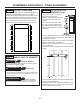
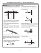
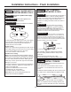
STEP 4 INSTALL CASE TRIM
The unit arrives with case trim for standard installation
attached. Flush installation case trim is provided.
Remove the factory installed case trim. Install new case
trim using supplied right hand and left hand case trim
pieces and case trim screws. Attach case trim to each
side of case as shown in illustration using case trim
screws in holes provided down each side of the case.
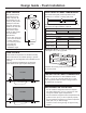
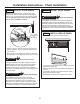
• Cut a 1” x 4” (2.54 x 10.16 cm)
block, 35” (88.9 cm) long.
• Measure and mark under the soffit,
5-1/4” from the front edge of the
cabinet.
• Secure the wood block to under
the soffit. From the bottom of the
block to the finished floor should
measure 84” (213.36 cm). See the
illustration.
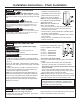
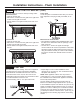
• The kit supplied with the unit contains 2 lag bolts and
4 toggles with bolts. The wall bracket will be attached
to the wall in 4 places.
• Measure the opening where the unit is to be installed.
Mark the center with a vertical line.
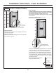
• Measure up 82” (208.28 cm)from the floor. Mark this
point on the wall.
• Using a level, draw a horizontal line on the wall at this
height.
• Locate at least 2 studs on the back wall. Mark these
points on the horizontal line.
• Place the bottom of the wall bracket with tabs on the
horizontal line. Align the center notch on the bracket
with the center line on the wall.
STEP 5 INSTALL ANTI-TIP
BRACKET (cont.)
82”
To Floor
WARNING
Tip Over Hazard.
The unit is top-heavy and must be secured to prevent
the possibility of tipping forward.
AVERTISSEMENT
Risque de
basculement
L’appareil ménager est beaucoup plus lourd en haut et il faut
le maintenir en place pour éviter la possibilité de son bascu-
lement vers l’avant.
ADVERTENCIA
Riesgo de Caídas
La unidad es pesada en su parte superior y se deberá ase-
gurar a fin de evitar posibles inclinaciones hacia adelante.
STEP 5
INSTALL ANTI-TIP BRACKET