
Installation


Design Guide - Flush Installation
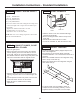
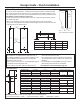
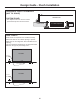
THE INSTALLATION SPACE
Water And Electrical Locations
The opening must be prepared with the electrical and
the cold water supply located as shown.
The Cutout Depth Must Be 26-3/16”
Wooden cleats are required for flush installation. See
Side Cleats on page 27. If 3/4” Overlay panels w/
90 degree door swing are to be used then cutout
depth must be 26-1/4”
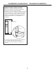
Additional Specifications
• A 115 volt 60Hz., 15 or 20 amp power supply is
required. An individual properly grounded branch
circuit or circuit breaker is recommended. Install
a properly grounded 3-prong electrical receptacle
recessed into the back wall. Electrical must be
located on the rear wall as shown.
NOTE: GFI (ground fault interrupter) is not
recommended.
• The water line can enter the opening through the
floor or back wall. The water line should be 1/4”
O.D. copper tubing or SmartConnect
™
kit between
the cold water line and water connection location,
long enough to extend to the front of the refrigerator.
Installation of an easily accessible shut-off valve in
the water line is required.
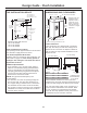
DIMENSIONS AND CLEARANCES
* Shipping height. The
refrigerator can be
adjusted to fit into a
cutout that is 85” in
height. Use leveling
legs and wheels for
a maximum 1” height
adjustment.
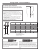
Product Clearances
These refrigerators are equipped with a 3-position
door stop. The factory-set 115° door swing can be
adjusted to 90° if clearance to adjacent cabinets or
walls is restricted. Only standard installation can be
adjusted to 130°.
24
90° Door Swing
115° Door Swing
*Finished Width
6"
5"
Electrical
Area
85" max
Finished
Opening
75" From Floor
to Bottom
of Electrical
Area
26-3/16"
7"
7"
3 1/2"
Water Supply
3 1/2"
36" Models 12"
42" Models 19"
48" Models 22-1/4"
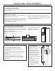
Allow minimum clearances for the freezer door
(Dimension A) and fresh food door (Dimension B) for
a full 115° door swing and to allow for pan removal.
For a 90° door swing, allow 4” min. clearance to a
wall, for framed and stainless steel models. Allow
5” min. clearance for professional series models.
If the 90° door stop position is used, pan access is
maintained, but pan removal is restricted.
Models A B C
36” 13” 15” 20-5/8”
42” 13” 19” 26-5/8”
48” 15” 20” 28-5/8”
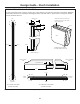
*84"
From
Floor
25-3/8" Framed Models
Depth Including Handles 26-7/8”
36", 42" or 48"
Frame to Frame
35", 41", or 47"
Case Width
*
83-1/2"
at
Rear
23-7/8"
Behind
Frame
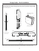
C
*Min. Distance
to Wall
*4” Stainless and
Trimmed Models.
5” Pro Series
B
A
*Finished cutout width must be:
39” for 36” models
45” for 42” models
51” for 48” models