Dimension Express Booklet Prepared On: 12/1/2010 . Prepared By: Job Information: From: Company: Address: Phone: Fax: Email: Job Name: Dutton--Hassan Tom Bogna Classic Custom Cabinets 11544 Sheldon street 818-767-1144 818-767-1278 tom@cbdcabinets.
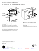
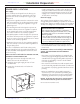
www.dexpress.com Mfr Guide Page 2 of 42 ZGU385NSMSS 12/1/2010 ZGU385LSMSS/ZGU385NSMSS GE Monogram® 36" Stainless Steel Gas Cooktop Dimensions and Installation Information (in inches) 21-3/16” Deep at Center 36-3/4” 3-3/4” 3-3/8” Min. from Cutout to Rear Vertical Combustibles 12” Min. from Cutout to Side Walls 19-1/8” 33-7/8” 2-1/2” Min. from Cutout to Front of Countertop 36” Min. Cabinet Base Note: The cooktop cutout is rectangular.
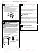
www.dexpress.com Cond Inst Page 3 of 42 ZGU385NSMSS Installation Preparation 12/1/2010 ADVANCE PLANNING INSTALLATION OPTIONS • Refer to “Installation Preparation” for information on appropriate placement and necessary clearances when planning installation. Cooktop and ZVB36 Downdraft Vent Combination Installation • Avoid placing cabinetry directly above cooktop when possible. • If cabinetry is used above cooking surface: – Use cabinets no more than 13″ deep.
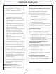
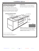
www.dexpress.com Cond Inst Page 4 of 42 ZGU385NSMSS Installation Preparation 12/1/2010 DIMENSIONS AND CLEARANCES 1. Overall cooktop dimensions: 3. Make sure the wall coverings, countertop and cabinets around the cooktop can withstand heat (up to 200°F) generated by the cooktop. 36-3/4″ 21-3/16″ deep at center 13″ max. 3-3/4″ 36″ min. 18″ min. 30″ min. 2. Use a 36″ or wider base cabinet. • Cut the opening in the countertop. To ensure accuracy, it is best to make a template for the opening.
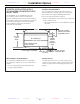
www.dexpress.com Cond Inst Page 5 of 42 ZGU385NSMSS Installation Preparation POWER SUPPLY LOCATIONS Install a manual shut-off valve in the gas line in an easily accessible location outside the cooktop. Be sure you know how and where to shut off the gas supply to the cooktop. Install the electrical outlet 12″ below the countertop. Gas supply: These cooktops are shipped from the factory set for either natural gas or LP gas. Check to be sure you have the correct cooktop for the type of gas being used.
www.dexpress.com Cond Inst Page 6 of 42 ZGU385NSMSS Installation Instructions 1 INSTALL THE COOKTOP A. Remove the screws on the sides of the cooktop burner box. Use those screws to attach the side mounting brackets. B. Insert the cooktop centered into the cutout opening. Make sure the front edge of the countertop is parallel to the cooktop. Check clearances at the front, back and sides. Cooktop 12/1/2010 2 INSTALL PRESSURE REGULATOR (cont.) C.
www.dexpress.com Cond Inst Page 7 of 42 Installation Options ZGU385NSMSS COOKTOP INSTALLATION WITH A 36″ MONOGRAM DOWNDRAFT VENT, MODEL ZVB36 COOKTOP REQUIREMENTS The countertop must have a deep flat surface to accommodate the cooktop and vent. Countertops with a rolled front edge and backsplash will not provide the flat surface area required. The installation of the downdraft vent with this cooktop requires careful consideration.
www.dexpress.com Cond Inst Page 8 of 42 Installation Options ZGU385NSMSS COOKTOP INSTALLATION OVER A MONOGRAM WARMING DRAWER, MODEL ZTD910 OR ZKD910 12/1/2010 POWER SUPPLY: These cooktops may be installed over a 30″ or 27″ Warming Drawer. Both the cooktop and the warming drawer must be installed according to each specific installation instruction. For accurate planning, review the Warming Drawer Installation Instructions in advance; order Pub. No. 49-8937.
www.dexpress.com Cond Inst Page 9 of 42 Installation Options ZGU385NSMSS COOKTOP INSTALLATION OVER A 30″ MONOGRAM SINGLE OVEN, MODEL ZET1 OR ZET938 12/1/2010 POWER SUPPLY These cooktops may be installed over the Monogram ZET1 or ZET938 single oven. Both the cooktop and the oven must be installed according to each specific installation instruction. For accurate planning, review the 30″ Oven Installation Instructions in advance; order Pub. No. 31-10633.
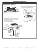
www.dexpress.com Mfr Guide Page 10 of 42 ZV800SJSS 12/1/2010 ZV800SJ/BJ – GE Monogram™ 36" Chimney Hood Dimensions and Specifications (in inches) Note: The vent hood canopy extends forward 5-7/8". The vent hood must be installed 24" min., and 30" max. above the cooking surface. The telescopic duct cover conceals the ductwork running from the top of the hood to the ceiling. The duct cover is sized to reach 8 ft. to 10 ft. ceiling heights.
www.dexpress.com Mfr Guide Page 11 of 42 ZV800SJSS 12/1/2010 ZV800SJ/BJ – GE Monogram™ 36" Chimney Hood Wall Mount Installations Installation Below a Cabinet These hoods may be installed onto a wall or below a wall cabinet. • Telescopic duct covers are provided to conceal the ductwork, running to the ceiling. • This hood can be installed for recirculation operation. No kits required. *20” Min. 24” Min. *The cabinet must measure at least 20" from the bottom frame to the inside top.
www.dexpress.com Mfr Guide Page 12 of 42 ZV800SJSS 12/1/2010 ZV800SJ/BJ – GE Monogram™ 36" Chimney Hood Cabinet Requirements Ductwork, Wiring This hood may be installed beneath a wall-mounted cabinet. • Both vented and recirculating operation can be accomplished in an under-cabinet installation. • If the cabinet has been installed, it must be removed so that wall framing supports can be added. • Determine the exact location of the vent hood.
www.dexpress.com Cond Inst Page 13 of 42 ZV800SJSS 12/1/2010 Design Information CONTENTS Design Information Product Dimensions and Clearances ..................................................3 Installation Options ................................................................................3 Advance Planning, Ductwork, Framing ..............................................4 Power Supply ..........................................................................................4 Duct Fittings........
www.dexpress.com Cond Inst Page 14 of 42 ZV800SJSS 12/1/2010 Installation Preparation ADVANCE PLANNING • Use metal ductwork only. These hoods must use 6” round duct. It can transition to 3-1/4” x 12”, reducing the maximum equivalent duct length to 75 feet. • Install a wall cap with damper or roof cap at the exterior opening. Order the wall or roof cap and any transition needed in advance. • Determine the exact location of the vent hood. • Plan the route for venting exhaust to the outdoors.
www.dexpress.com Cond Inst Page 15 of 42 ZV800SJSS 12/1/2010 Installation Preparation DUCT FITTINGS Use this chart to compute maximum permissable lengths for duct runs to outdoors. Duct Piece NOTE: Do not exceed maximum permissable equivalent lengths! Maximum duct length: 100 foot for 6” round duct 75 foot for 3-1/4” x 12” duct Flexible ducting: If flexible metal ducting is used, all the equivalent feet values in the table should be doubled.
www.dexpress.com Cond Inst Page 16 of 42 ZV800SJSS 12/1/2010 Installation Preparation WALL MOUNT INSTALLATIONS Wall Mount ZV800 Installation Heights These hoods may be installed onto a wall or below a wall cabinet. • Telescopic duct covers are provided to conceal the ductwork, running to the ceiling. • This hood can be installed for recirculating operation. No kits required. 24” Min. 30” Max. 36” Min. The vent hood must be installed 24” min. and 30” max. above the cooking surface.
www.dexpress.com Cond Inst Page 17 of 42 ZV800SJSS 12/1/2010 Installation Instructions WALL-MOUNTED INSTALLATION—VENTED TO THE OUTSIDE DUCTWORK, WIRING LOCATIONS Determine the exact location of the vent hood. • Locate the template packed with the literature. – Measure 36” from the floor to the top of the cooking surface. Add hood installation height determined on page 7. Mark that location. – Use a level to draw a straight pencil line on the wall.
www.dexpress.com Cond Inst Page 18 of 42 ZV800SJSS 12/1/2010 Installation Instructions WALL-MOUNTED INSTALLATION—VENTED TO THE OUTSIDE 6 CONNECT DUCTWORK Air flow • Install ductwork, making connections in direction of airflow as illustrated. • Push duct over the exhaust outlet and damper. • Secure joints in ductwork with sheetmetal screws. • Wrap all duct joints with duct tape for an airtight seal. • Use duct tape to seal the flange connections.
www.dexpress.com Cond Inst Page 19 of 42 ZV800SJSS 12/1/2010 Installation Instructions WALL-MOUNTED INSTALLATION—RECIRCULATING 1 INSTALL FRAMING FOR HOOD SUPPORT DUCTWORK, WIRING LOCATIONS • Determine the exact location of the vent hood. • Locate the template packed with the literature. • Measure 36” from the floor to the top of the cooking surface. Add hood installation height determined on page 7. Mark that location. IMPORTANT: Framing must be capable of supporting 100 lbs.
www.dexpress.com Cond Inst Page 20 of 42 ZV800SJSS 12/1/2010 Installation Instructions UNDER-CABINET INSTALLATION CABINET REQUIREMENTS DUCTWORK, WIRING This hood may be installed beneath a wall-mounted cabinet. • If the cabinet has been installed, it must be removed so that wall framing supports can be added. • Determine the exact location of the vent hood. • Locate the Rear Wall Template packed with the literature. • Measure 36” from the floor to the top of the cooking surface.
www.dexpress.com Cond Inst Page 21 of 42 ZV800SJSS 12/1/2010 Installation Instructions UNDER-CABINET INSTALLATION 1 INSTALL FRAMING FOR HOOD SUPPORT IMPORTANT: Framing must be capable of 2 PREPARE THE HOOD • Remove the hood from the box. Remove packaging and tape. supporting 100 lbs. Electrical panel Remove 2 side cover screws ViewFrom from rear View Rear cleats Cleats • Remove one screw on each side of the cover on the electrical panel. Lift off the cover and set aside with screws.
www.dexpress.com Cond Inst Page 22 of 42 ZV800SJSS 12/1/2010 Installation Instructions UNDER-CABINET INSTALLATION 3 CUT THE OPENING 4 INSTALL SIDE “L” BRACKETS If the cabinet has been installed, remove it from the wall. • Use the Top Cabinet Template to locate and cut a hole in the bottom of the cabinet. • If necessary, place the template on top of the cabinet to accurately cut a matching hole. • Install the cabinet onto the wall.
www.dexpress.com Mfr Guide Page 23 of 42 ZE2160SF 12/1/2010 ZE2160SF – GE Monogram® Microwave Oven Dimensions (in inches) 25-1/2" ± 1/8" Exterior Dimensions (in inches) WxHxD 16-3/4" ± 1/16" *Depth excludes handle. Accessory Trim Kits Top Duct 22" min. receptacle in cabinet 19-1/2" min.
www.dexpress.com Cond Inst Page 24 of 42 ZE2160SF 12/1/2010 Installation Instructions 2 INSTALL BOTTOM BRACKET AND BOTTOM DUCT 1 CUTOUT DIMENSIONS Models 27″ 30″ Height 16 ⁄ ″ 16 ⁄ ″ Width 251⁄2″ 251⁄2″ 191⁄2″ or 22″ 191⁄2″ or 22″ 34 Depth (min.)* A Fit the tab on the bottom bracket into the slot on the back of the bottom duct, and push down until the bracket is flush with the bottom of the duct. Fasten the bottom bracket to the bottom duct by using two bronze round-head screws.
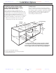
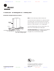
1/2" Min. www.dexpress.com Mfr Guide Page 25 of 42 ZET2SMSS 12/1/2010 ZET2SM GE Monogram® 30” Built-In Double Oven Dimensions and Installation Information (in inches) 23-1/2" Min. KW Rating 240V 208V 8.6 7.8 Locate Junction Box 47" Above Cutout Floor, Within 5" of Right Rear Wall Breaker Size 240V 40 Amps 208V 40 Amps Installation Flexibility These ovens may be installed in combination with a Monogram warming drawer. 51-13/16" Min. 51-15/16" Max. 28-1/2" Min. 28-5/8" Max.
www.dexpress.com Cond Inst Page 26 of 42 ZET2SMSS 12/1/2010 Installation Instructions IMPORTANT SAFETY INSTRUCTIONS For Your Safety • Be sure your oven is installed properly by a qualified installer or service technician. • Make sure the cabinets and wall coverings around the oven can withstand the temperatures (up to 200°F [93.3°C]) generated by the oven. • Be sure the oven is securely installed in a cabinet that is firmly attached to the house structure.
www.dexpress.com Cond Inst Page 27 of 42 ZET2SMSS 12/1/2010 Installation Instructions A1 Cutout for Single Built-In Oven Cutout Width CUTOUT 28 WIDTH 1/2” Min. 28 5/8” 1/2" MIN. 28 Max. 28 5/8" MAX.cm) (72.4 to 72.7 ALLOW 11/16" FOR OVERLAP OF THE Allow 11/16” OVEN OVER SIDE (1.75 for EDGES OFcm) CUTOUT overlap of oven over side edges of cutout Opening Between THE OPENING Inside Walls BETWEEN INSIDE Must Be WALLS MUST BEAt ATLeast LEAST 28 281/2"WIDE 1/2” (72.4 cm) Wide Junction Box Location (19.
www.dexpress.com Cond Inst Page 28 of 42 ZET2SMSS 12/1/2010 Installation Instructions A2 Cutout for Double Built-In Oven Cutout Width 28 1/2” CUTOUT (72.4 cm) Min. WIDTH 28 1/2" MIN. 28 5/8” 28 5/8" MAX. (72.7 cm) Max. 7 3/4” (19.7 cm) Max. Cabinet Width 30” (76.2 cm) 5" Junction Box JUNCTION BOX Location LOCATION ALLOW 11/16" FOR OVERLAP Allow OF THE11/16” OVEN OVER (1.8SIDE cm) EDGES for OF CUTOUT overlap of oven over side edges of cutout Allow a minimum ALLOW A MINIMUM OF 21" of 21” (53.
www.dexpress.com Cond Inst Page 29 of 42 ZET2SMSS 12/1/2010 Installation Instructions A3 Cutout for Single Built-In Oven Under Counter Gas or electric cooktops may be installed over this oven. See cooktop installation instructions for cutout size. See label on top of oven for approved cooktop models. 240V / 208V Junction Box Location (junction box may be in adjacent cabinet) 25” (63.5 cm) Top and/or side fillers may be necessary if unit is positioned between existing cabinets.
www.dexpress.com Cond Inst Page 30 of 42 ZET2SMSS 12/1/2010 Cabinetry A4 Single Oven Cutout A5 for Installation Over a Monogram Warming Drawer Double Oven Cutout for Installation Over a Monogram Warming Drawer Anti-Tip Block Against Rear Wall Per Warming Drawer Requirement Anti-Tip Block Against Rear Wall Per Warming Drawer Requirement 2” (5.1 cm) Min. 2” (5.1 cm) Min. NOTE: Install the oven only with specific models listed on the label located on top of Per Warming the oven.
www.dexpress.com Cond Inst Page 31 of 42 ZET2SMSS 12/1/2010 Cabinetry A7 Single Oven Cutout A8 for Installation Below a Monogram Advantium or Microwave Oven Per Advantium or Microwave Oven Requirement Single Oven Cutout for Installation Between a Monogram Advantium or Microwave Oven and a Monogram Warming Drawer Per Advantium or Microwave Oven Requirement 2” (5.1 cm) Min. Note: Install the oven only with specific models listed on the label located on top of the oven. 2” (5.1 cm) Min. 2” (5.
www.dexpress.com Cond Inst Page 32 of 42 ZET2SMSS 12/1/2010 Installation Instructions B Electrical Connections ATTENTION INSTALLER All electric wall ovens must be hard wired (direct wired) into an approved junction box. A plug and receptacle is NOT permitted on these products. B1 Turn off the circuit breaker or remove fuses to the oven branch circuit.
www.dexpress.com Mfr Guide Page 33 of 42 ZISP420DXSS 12/1/2010 ZISP420DXSS GE Monogram® 42" Built-In Professional Side-by-Side Refrigerator with Dispenser and Water Filter The Installation Space Dimensions and Installation Information (in inches) 41" Case Width *84" from Floor to Top Frame *83-1/2" at Rear * Shipping height. The refrigerator can be adjusted to fit into cutout that * Shipping height.aThe refrigerator can be adjusted is 83-1/2" min. to to fit into a cutout that is 84-1/2” max.
www.dexpress.com Cond Inst Page 34 of 42 ZISP420DXSS 12/1/2010 Design Guide THE INSTALLATION SPACE DIMENSIONS AND CLEARANCES 36" Models 12" 42" Models 18" 48" Models 20" 25-3/8" Framed Models 25-3/4" Stainless Steel Models * Shipping height. The refrigerator can be adjusted to fit into a cutout that is 83-1/2" min. to 84-1/2" max. *84" From height. Note that the Floor to top case trim at the Top Frame front is 1/2" higher and will overlap upper cabinetry or soffit.
www.dexpress.com Cond Inst Page 35 of 42 ZISP420DXSS 12/1/2010 Design Guide Refrigerator Frameless Cabinets: The case trim overlaps cabinets at the top and sides. Therefore, frameless cabinets may require filler strips to prevent interfeence with cabinet door swing. The opening must allow for filler strips.
www.dexpress.com Cond Inst Page 36 of 42 ZISP420DXSS 12/1/2010 Design Guide Frameless Cabinets: The case trim overlaps cabinets at the top and sides. Therefore, frameless cabinets may require filler strips to prevent interference with cabinet door swing. The opening must allow for filler strips.
www.dexpress.com Cond Inst Page 37 of 42 ZISP420DXSS 12/1/2010 Design Guide CUSTOMIZATION BASICS: Framed Or Overlay Panels, Custom Handles and Accessory Kits Professional Style Stainless Steel Refrigerators Stainless steel wrapped refrigerators have beveled edges and professional-style handles. These models are shipped ready for installation. Overlay panels You may also choose to install custom overlay panels from your cabinet manufacturer.
www.dexpress.com Cond Inst Page 38 of 42 ZISP420DXSS 12/1/2010 Design Guide 1/4" FRAMED PANEL DIMENSIONS 5/16" Trim Reveal Door If you choose to install framed panels, they must be cut to the dimensions shown. The panels will slide into the frame on the door and grille. 1/4" Panel Non-Dispenser Models If the custom panel is less than 1/4" thick and it fits loosely in the door frame it can be backed up with a piece of filler material or foam tape to improve the fit.
www.dexpress.com Cond Inst Page 39 of 42 ZISP420DXSS 12/1/2010 Design Guide 3/4" OVERLAY PANEL DIMENSIONS Overlay Panel Door For a more custom appearance, overlay panels may be installed on trimmed models. The overlay panel must be secured to a 1/4" thick backer panel which slides into the trim. A spacer panel 0.10" thick must be placed between the overlay and backer panel. Assemble the panels with glue and screws: • Center the spacer panel on the backer panel, left to right and top to bottom.
www.dexpress.com Cond Inst Page 40 of 42 ZISP420DXSS 12/1/2010 Design Guide DISPENSER MODELS: RAISED OVERLAY PANEL DESIGN 1/4" Backer Panel .10" Spacer 3/4" Overlay Panel When a raised panel design is to be used, a custom wide middle rail is required to accept the dispenser trim. • The middle rail must be wide enough to allow for the dispenser trim to overlap the opening. • The middle rail must be 1.100" total thickness to accept the dispenser trim.
www.dexpress.com Cond Inst Page 41 of 42 ZISP420DXSS 12/1/2010 Design Guide 24" SIDE PANELS Side panels must be used whenever the sides of the refrigerator will be exposed. The 1/4" side panels will slip into the side case trim. Secure the panels to the refrigerator with stick-on *84" hook and loop fastener strips. Order the side panels from the cabinet manufacturer. • Cut a notch in the top front corner as shown to allow clearance for corner keys in the front side trim.
www.dexpress.com Cond Inst Page 42 of 42 ZISP420DXSS 12/1/2010 Installation Instructions • Remove the six 7/16" bolts securing the straps to the skid. STEP 1 REMOVE PACKAGING CAUTION: The refrigerator is much heavier at the top than at the bottom—be careful when moving. When using a hand truck, handle from the side only. Toekick CAUTION: PRUDENCE: Le réfrigérateur est beaucoup plus lourd en haut qu’en bas. Il faut être prudent lors des déplacements.