
Installation Instructions

31-7000138 Rev. 0 17
Installation Instructions
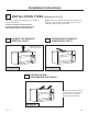
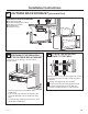
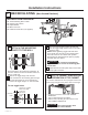
Snip all 4
webs on each
knockout panel
and remove the
metal knockouts
for rear airflow.
Locate the two “knockout” plates, on the rear
oven panel, near the top of the oven.
Using tin snips, carefully cut the web area from
the two holes side-by-side (that secure the
knockouts to the oven). Cut all four webs on both
rear knockouts; this will allow the ventilation fan
airflow to exhaust out the rear of the oven.
CAUTION
Be sure to trim the sharp
edges from the openings after removing the
knockout plates.
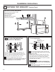
AFTER:
Fan Blade
Openings
Facing Back
7
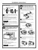
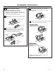
Place the blower unit back into the opening.
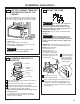
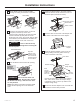
9
Insert the tabs on each side of the damper into
the holes at the inside rear of the adaptor.
8
Roll the blower unit 90° so that fan blade
openings are facing out the back of the oven.
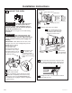
5
Replace the blower plate in the same position
as before with the screws. Attach the cover on
the blower plate (include one screw).
Before Rolling
After Rolling
End A
End B
Back of
Oven
Back of
Oven
WARNING
Risk of electric shock can
cause injury or death. Do not pull or stretch
the blower unit wiring. make sure the wires
are not pinched..
NOTE: The blower unit exhaust openings should
match exhaust openings on rear of microwave
oven.
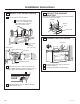
Oven Rear Panel
6
Attach the exhaust adaptor to the rear of the
oven by sliding it into the guides at the top
center of the back of the oven.
10
Secure the exhaust adaptor to the oven with the
two bronze metal screws provided.
11
Push in securely until it is in the lower locking
tabs. Take care to assure the damper hinge
is installed so that it is at the top and that the
damper swings freely.
Slide
exhaust
adaptor into
guides on
oven rear.
Exhaust Adaptor
Damper
(hinge side up)
Locking
Tabs
Guides
Back of Oven
Exhaust
Adaptor
Screws
Blower Plate
Back of Oven
Blower Plate Screws
Cover Plate
Cover Plate