Installation Instructions 27" and 30" Warming Drawers Models: ZKD910 ZTD910 31-10700 08-08 JR
Safety Information WARNING BEFORE YOU BEGIN Read these instructions completely and carefully. • • This appliance must be properly grounded. See “Grounding the Appliance.” IMPORTANT — Save these instructions for local inspector’s use. For Monogram local service in your area, 1.800.444.1845. IMPORTANT — Observe all governing codes and ordinances. • Note to Installer — Be sure to leave these instructions with the Consumer.
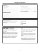
Design Information CONTENTS Installation Instructions Step 1, Anti-Tip Brackets......................................................9 Step 2, Install Warming Drawer ......................................9 Custom Panel Accessory Kit Installation ..........10, 11 Professional Style Panel Accessory Kit Installation..........................................12, 13 Design Information Models Available......................................................................3 Accessories .............................
Design Information PRODUCT DIMENSIONS AND CLEARANCES 23-1/4" A Drawer Open 1" 10-1/2" 9" C B Including Handle Dimensions A B C ZTD910 22" 26" 30" ZTD910 w/ZXD30P 23-1/4" 27-1/2" 30" ZKD910 22" 26" 26-3/4" ADVANCE PLANNING • Electrical power cord is located on the right side of the warming oven. Locate the outlet within reach of the 56" long power cord in an adjacent cabinet, within 42" of the right side or 16" from the left side of the cutout.
Design Information GROUNDING THE APPLIANCE Please read carefully. FOR PERSONAL SAFETY, THIS APPLIANCE MUST BE PROPERLY GROUNDED. Do not use an extension cord or adapter plug with this appliance. Follow National electrical codes or prevailing local codes and ordinances. This warming drawer must be supplied with 120V, 60Hz, and connected to an individual, properly grounded branch circuit, and protected by a 15 or 20 amp circuit breaker or time delay fuse. Recessed Receptacle 7" Max.
Installation Preparation MATERIALS REQUIRED (provided) TOOLS REQUIRED Hand Saw 4 Wood Screws Safety Glasses MATERIALS REQUIRED (not provided) Drill and 1/16" Bit Measuring Tape Level 2x2 or 2x4 Wood Block for Anti-Tip Security Phillips Screwdriver 2x2 or 2x4 Lumber for Runners Adhesive or other hardware for installing runners or shelf to support warmer drawer Runners must be level, rigidly mounted and capable of supporting 150 pounds. REMOVE PACKAGING •Place carton on a flat surface.
Installation Preparation INSTALLATION OPTIONS Installation Below a Double Oven Installation Below a Single Oven 23-1/2" Min. Inside 23-1/2" Min. Inside 2x2 or 2x4 Anti-Tip Block Against Rear Wall, 9" From Floor to Bottom of Block 2x2 or 2x4 Anti-Tip Block Against Rear Wall, 9" From Floor to Bottom of Block Oven Cutout Oven Cutout 2" Min. 9" 2" Min. Allow 5/8" Overlap on All Sides 9-1/4" Allow 5/8" Overlap on All Sides 23-1/4" 23-1/4" 9" 9-1/4" 10-1/2" 10-1/2" A 1" Min.
Installation Preparation INSTALLATION BELOW A COUNTERTOP Electrical Outlet 16" Max. From Left Side Install 2x4 or 2x2 Anti-Tip Block Against Rear Cabinet Wall 9" From Floor to Bottom of Block Electrical Outlet Flush With Side of Cabinet 7" Max. Electrical Outlet 42" Max. From Right Side 1-1/2" Cabinet Top 25" 7" Install a Solid Barrier Below a Cooktop See Note 1" Min.* 36" Countertop Height 9" 9-1/4" A Solid Barrier Dimensions 1/4" Air Gap ZTD910 ZKD910 23-1/2" Min.
Installation PROVIDE CABINET SUPPORT 2"x4" or Equivalent Runners 2"x4" or Equivalent Runners 23-1/2" 23-1/2" 25" 30" 22" 27" IMPORTANT: When installed below a single or double oven, check to be sure that any oven supports above the cutout do not obstruct the 23-1/2" required depth of the warming drawer cutout. •The support must be level and rigidly mounted, flush with the bottom edge of the cutout. – There is no way to level the drawer once it has been installed. Be sure supports are level.
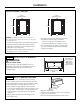
WARMING DRAWER CUSTOM PANEL ACCESSORY KIT Installation Instructions ZXD27B AND ZXD30B For installation of 27" and 30" wide warming drawer custom panel and custom handle. BEFORE YOU BEGIN STEP 1 PREPARE DRAWER FOR PANEL INSTALLATION Read these instructions completely and carefully. • IMPORTANT • Open the drawer fully. • Turn the warming drawer off. – Save these instructions for local inspector’s use. Observe all governing codes and ordinances.
Installation STEP 4 STEP 6 SECURE CUSTOM PANEL TO METAL MOUNTING PANEL Turn the assembly appearance side up. • Use plastic to wood adhesive to secure the lamp jewel to the front of the wood panel. On the side with the bulge, (see illustration) apply a small bead of adhesive around the outside edge. Place the jewel into the drilled hole. • Lay the custom panel, appearance side down, on a clean surface.
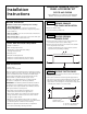
Installation Instructions PROFESSIONAL STYLE PANEL ACCESSORY KIT ZXD30P BEFORE YOU BEGIN STEP 2 REMOVE ORIGINAL DRAWER FRONT Read these instructions completely and carefully. IMPORTANT • Remove the three screws from the bottom of the drawer edge. • Remove the four screws on the inside of the drawer at the top. Retain all screws. – Support the drawer front as you remove screws to prevent the front panel from falling. – Save these instructions for local inspector’s use.
Notes 13
Notes 14
Notes 15
NOTE: While performing installations described in this book, safety glasses or goggles should be worn. For Monogram® local service in your area, call 1.800.444.1845. NOTE: Product improvement is a continuing endeavor at General Electric. Therefore, materials, appearance and specifications are subject to change without notice. GE Consumer & Industrial 31-10700 08-08 JR Printed in the United States Appliances General Electric Company Louisville, KY 40225 ge.