Installation Instructions If you have questions, call 800.626.2000 or visit our website at: www.monogram.com 36” Chimney Vent Hood ZV800 49-80267-3 01-13 GE monogram.
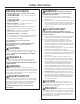
Safety Information BEFORE YOU BEGIN WARNING: TO REDUCE THE RISK OF FIRE, ELECTRICAL SHOCK OR INJURY TO PERSONS, OBSERVE THE FOLLOWING: A. Use this unit only in the manner intended by the manufacturer. If you have any questions, contact the manufacturer. B. Before servicing or cleaning unit, switch power off at the service panel and lock service panel to prevent power from being switched on accidentally. If the service panel cannot be locked, fasten a tag or prominent warning label to the panel.
Design Information CONTENTS Wall-Mounted Installation – Recirculating Ductwork, Wiring Locations .................................................................... 14 Step 1, Install Framing for Hood Support ......................................... 14 Step 2, Install Mounting Bracket ........................................................... 15 Step 3, Prepare the Hood ......................................................................... 15 Step 4, Mount the Hood ...................................
Installation Preparation ADVANCE PLANNING l’air correctement. Il ne faut pas évacuer l’air correctement. Il ne faut pas évacuer l’air dans l’espace entre les parois d’un mur, un plafond ou un grenier, un espace sanitaire ou un garage. Use metal ductwork only. These hoods must use 6” round duct. It can transition to 3-1/4” x 12”, reducing the maximum equivalent duct length to 75 feet. Install a wall cap with damper or roof cap at the exterior opening.
Installation Preparation DUCT FITTINGS Use this chart to compute maximum permissable lengths for duct runs to outdoors. Duct Piece NOTE: Do not exceed maximum permissable equivalent lengths! Maximum duct length: 100 foot for 6” round duct 75 foot for 3-1/4” x 12” duct Flexible ducting: If flexible metal ducting is used, all the equivalent feet values in the table should be doubled. The flexible metal duct should be straight and smooth and extended as much as possible. DO NOT use flexible plastic ducting.
Installation Preparation TOOLS AND MATERIALS REQUIRED (NOT SUPPLIED) Tape measure Knife Spirit level Spirit level Measuring Tape Wire cutter/stripper Wire nuts Electric drill with 1/8” and 3/8” bits Phillips and flat blade screwdrivers Hammer Pliers Electric drill Pliers with 1/8” Safety glasses and 3/8” Bits Duct tape Tape to mount template Gloves to protect against sharp edges 120V 60Hz.
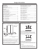
Installation Preparation WALL MOUNT INSTALLATIONS Wall Mount ZV800 Installation Heights These hoods may be installed onto a wall or below a wall cabinet. Telescopic duct covers are provided to conceal the ductwork, running to the ceiling. This hood can be installed for recirculating operation. No kits required. Actual Ceiling Height 24” Min. 30” Max. 36” Min. The vent hood must be installed 24” min. and 30” max. above the cooking surface.
Installation Preparation CHECK INSTALLATION HARDWARE Locate the hardware accessory box packed with the hood and check contents.
Installation Instructions :$// 02817(' ,167$//$7,21³9(17(' 72 7+( 2876,'( DUCTWORK, WIRING LOCATIONS Determine the exact location of the vent hood. Locate the template packed with the literature. – Measure 36” from the floor to the top of the cooking surface. Add hood installation height determined on page 7. Mark that location. –Use a level to draw a straight pencil line on the wall. 1 INSTALL FRAMING FOR HOOD SUPPORT IMPORTANT ³ Framing must be capable of supporting 100 lbs. 8"6”Min. Ductwork min.
Installation Instructions :$// 02817(' ,167$//$7,21³9(17(' 72 7+( 2876,'( 2 INSTALL MOUNTING BRACKET 3 INSTALL DUCT BRACKET This vent hood must be secured to the horizontal support or wall studs. :LWK WKH WHPSODWH WDSHG LQ SODFH XVH D SXQFK WR mark all mounting screw locations. Drill 1/8” pilot holes at the 6 punched locations. Remove the template. The 2 holes in the support bracket holes must enter studs or the horizontal support. The duct bracket must be intalled against the ceiling.
Installation Instructions :$// 02817(' ,167$//$7,21³9(17(' 72 7+( 2876,'( 4 PREPARE THE HOOD 5 MOUNT THE HOOD Remove the hood from the box. Remove packaging and tape. Electrical panel Install a wood screw on each side of the mounting frame Remove 2 side cover screws Mounting bracket Lift the hood onto the mounting bracket. Check to be sure it is level. Install wood screws through the hood and into the wall on each side of the mounting bracket.
Installation Instructions :$// 02817(' ,167$//$7,21³9(17(' 72 7+( 2876,'( 6 CONNECT DUCTWORK Air flow Install ductwork, making connections in direction of airflow as illustrated. Push duct over the exhaust outlet and damper. Secure joints in ductwork with sheetmetal screws. Wrap all duct joints with duct tape for an airtight seal. Use duct tape to seal the flange connections. Duct tape over seam and screw CAUTION: Do not use sheet metal screws at the hood flange connection.
Installation Instructions :$// 02817(' ,167$//$7,21³9(17(' 72 7+( 2876,'( 8 INSTALL DUCT COVERS 9 INSTALL FILTERS Place the decorative duct covers on top of the hood. Mounting screws NOTE: The inside (upper) duct piece has holes on one end. The holes are intended for use when the hood is installed for recirculating purposes. Slide the vented end into the outer piece, the vent holes should not be visible in this installation. Remove protective film on the filters.
Installation Instructions :$// 02817(' ,167$//$7,21³5(&,5&8/$7,1* DUCTWORK, WIRING LOCATIONS 1 INSTALL FRAMING FOR HOOD SUPPORT Determine the exact location of the vent hood. Locate the template packed with the literature. Measure 36” from the floor to the top of the cooking surface. Add hood installation height determined on page 7. Mark that location. IMPORTANT: Framing must be capable of supporting 100 lbs. View ViewFrom from Rear rear Cleats cleats Ceiling 1" x 6” 6" min. Min.
Installation Instructions :$// 02817(' ,167$//$7,21³5(&,5&8/$7,1* 2 INSTALL MOUNTING BRACKET 3 PREPARE THE HOOD This vent hood must be secured to the horizontal support or wall studs. With the template taped in place, use a punch to mark all mounting screw locations. Drill 1/8” pilot holes at the 6 punched locations. Remove the template. The 2 holes in the support bracket holes must enter studs or the horizontal support. Remove the hood from the box. Remove packaging and tape.
Installation Instructions :$// 02817(' ,167$//$7,21³5(&,5&8/$7,1* 4 MOUNT THE HOOD Install a wood screw on each side of the mounting frame 5 SIZE AND CUT DUCT PIECE (cont.) Cut the duct piece to size and slip onto the bottom of the duct connector. Use duct tape to seal and secure the duct piece to the connector. Mounting bracket Lift the hood onto the mounting bracket. Check to be sure it is level. Install wood screws through the hood and into the wall on each side of the mounting bracket.
Installation Instructions :$// 02817(' ,167$//$7,21³5(&,5&8/$7,1* 6 CONNECT ELECTRICAL Remove junction box cover and knockout. Use a conduit connector to secure the conduit to the junction box. Connect white leads to branch circuit white lead. Connect black leads to branch circuit black lead. Connect green/yellow leads to branch circuit green lead or bare ground lead. Secure all connections with wire nuts on each electrical connector. Push wires into junction box and replace cover.
Installation Instructions :$// 02817(' ,167$//$7,21³5(&,5&8/$7,1* 8 INSTALL FILTERS 9 FINALIZE INSTALLATION 5HPRYH DOO SDFNDJLQJ PDWHULDOV 5HIHU WR WKH 2ZQHU·V 0DQXDO IRU RSHUDWLQJ instructions. Charcoal filter Remove protective film on the filters. Install the black charcoal filter into the center opening. Metal grease filters Tip filters into the slots at the rear of the opening. Lift the filter lock and pull forward until the filter rests in the slots.
Installation Instructions UNDER-CABINET INSTALLATION CABINET REQUIREMENTS DUCTWORK, WIRING This hood may be installed beneath a wall-mounted cabinet. If the cabinet has been installed, it must be removed so that wall framing supports can be added. Determine the exact location of the vent hood. Locate the Rear Wall Template packed with the literature. Measure 36” from the floor to the top of the cooking surface. Add the pre-determined hood installation height. Mark that location.
Installation Instructions UNDER-CABINET INSTALLATION 1 INSTALL FRAMING FOR HOOD SUPPORT 2 PREPARE THE HOOD Remove the hood from the box. Remove packaging and tape. IMPORTANT: Framing must be capable of supporting 100 lbs. Electrical panel Remove 2 side cover screws View ViewFrom from Rear rear Cleats cleats Remove one screw on each side of the cover on the electrical panel. Lift off the cover and set aside with screws. 1" x 6” 6" min. Min.
Installation Instructions UNDER-CABINET INSTALLATION 3 CUT THE OPENING 4 INSTALL SIDE “L” BRACKETS If the cabinet has been installed, remove it from the wall. Use the Top Cabinet Template to locate and cut a hole in the bottom of the cabinet. If necessary, place the template on top of the cabinet to accurately cut a matching hole. Install the cabinet onto the wall. The cabinet must be firmly secured to the wall and be capable of supporting 100 lbs.
Installation Instructions UNDER-CABINET INSTALLATION 6 MOUNT THE HOOD 7 COMPLETE THE INSTALLATION AND CONNECT DUCTWORK Install a wood screw on each side of the mounting frame Install 2 Screws into Each Side Bracket Carefully, lift the hood into the cabinet. Guide the hood upwards to meet the ductwork. Drive 2 screws into each side bracket. Be sure the screws engage the filler blocks or the cabinet bottom.
Installation Instructions UNDER-CABINET INSTALLATION 8 CONNECT ELECTRICAL 10 INSTALL FILTERS WARNING: If house wiring is not 2-wire with a ground wire, a ground must be provided by the installer. When house wiring is aluminum, be sure to use U.L. approved anti-oxidant compound and aluminum-to-copper connectors. Remove protective film on the filters. ADVERTISSEMENT : Si la maison n’est pas câblee avec deux fils et un fil de terre, l’installateur doit installer un fil de terre.
NOTE: While performing installations described in this book, safety glasses or goggles should be worn. For Monogram® local service in your area, call 1.800.444.1845. NOTE: Product improvement is a continuing endeavor at General Electric. Therefore, materials, appearance and specifications are subject to change without notice.