Installation Instructions 36″ Island Chimney Vent Hood ZV925 49-80329 05-06 JR
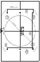
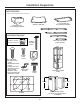
04-06 JR 49-80406 Printed in Italy 7-1/16″ to Centerline of Holes Drill 3/16″ Pilot Holes Approx. 1-1/2″ Deep Cut a 1″ Dia. Wire Access Hole 2″ 1/ 8- . ia D 10-1/16″ to Centerline of Holes 36″ Hood Template FRONT OF HOOD Cut a 1″ Dia. Wire Access Hole 7-1/16″ to Centerline of Holes Drill 3/16″ Pilot Holes Approx.
Installation Instructions WARNING: TO REDUCE THE BEFORE YOU BEGIN RISK OF FIRE, ELECTRICAL SHOCK OR INJURY, OBSERVE THE FOLLOWING: A. Use this unit only in the manner intended by the manufacturer. If you have any questions, contact the manufacturer. B. Before servicing or cleaning unit, switch power off at the service panel and lock service panel to prevent power from being switched on accidentally. If the service panel cannot be locked, fasten a tag or prominent warning label to the panel.
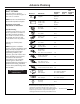
Design Information CONTENTS Design Information Product Dimensions ..............................................................................3 Advance Planning Advance Planning ..................................................................................4 Power Supply ............................................................................................4 Duct Fittings ............................................................................................
Advance Planning ADVANCE PLANNING POWER SUPPLY Ductwork Planning •These vent hoods are equipped for 8″ round ductwork. •Determine the exact location of the vent hood. •Plan the route for venting exhaust to the outdoors. •Use the shortest and straightest duct route possible. For satisfactory performance, duct run should not exceed 100 ft. equivalent length for any duct configurations. •Refer to “Duct Fittings” chart to compute the maximum permissible length for duct runs to the outdoors.
Advance Planning DUCT FITTINGS Use this chart to compute maximum permissible lengths for duct runs to outdoors. NOTE: Do not exceed maximum permissible equivalent lengths! Maximum duct length: 100 foot for 8″ round duct Flexible ducting: If flexible metal ducting is used, all the equivalent feet values in the table should be doubled. The flexible metal duct should be straight and smooth and extended as much as possible. DO NOT use flexible plastic ducting.
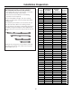
Installation Preparation Possible Hood Mounting Ceiling Installation Frame Trim Piece Height Height (inches) Height (inches) Needed 7′ 11″ 26 30 1/2 A 8′ 27 30 1/2 A 8′ 1″ 24 34 1/2 B 8′ 1″ 28 30 1/2 A 8′ 2″ 25 34 1/2 B 8′ 2″ 29 30 1/2 A 8′ 3″ 26 34 1/2 B 8′ 3″ 30 30 1/2 A 8′ 4″ 27 34 1/2 B 8′ 5″ 24 38 1/2 C 8′ 5″ 28 34 1/2 B 8′ 6″ 25 38 1/2 C 8′ 6″ 29 34 1/2 B 8′ 7″ 26 38 1/2 C 8′ 7″ 30 34 1/2 B 8′ 8″ 27 38 1/2 C 8′ 9″ 24 42 1/2 D 8′ 9″ 28 38 1/2 C 8′ 10″ 25 42 1/2 D 8′ 10″ 29 38 1/2 C 8′ 11″ 26 42 1/2 D 8
Installation Preparation TOOLS AND MATERIALS REQUIRED 3/8″ swivel socket or pivoting hex socket with 6″ extensions (NOT SUPPLIED) Duct tape Hammer Wire cutter/stripper Key hole saw Pencil and tape measure Electric or battery-operated drill and 3/16″ bits, Phillips and flat blade screwdriver bits. 8″ round metal duct, length to suit installation. Safety glasses Wire nuts Spirit level Flashlight Saber saw or sawsall Phillips and flat blade screwdrivers Strain relief for junction cover.
Installation Preparation PARTS PROVIDED Locate the parts packed with the hood. Stainless steel filter Air deflector for recirculating installation 1 charcoal filter for recirculating installation HARDWARE PACKAGE Locate and check contents. Screws shown actual size.
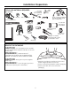
Installation Preparation CONSTRUCT CEILING SUPPORT • The hood should extend beyond the front and rear edge of the cooking appliance. • The duct in the ceiling must be centered over the cooktop. Plan the Location of the Hood and Ductwork • Use a plumb bob to check the location. The countertop/cooktop below the hood must be centered with the hood.
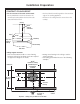
Installation Preparation CONSTRUCT CEILING SUPPORT CONTINUED EXAMPLE B 10-1/16″ install cross-framing symmetrically over duct/cooktop centerline 16″ joist spacing 7-1/16″ 2x4 cross framing 8″ duct Front of hood Align duct to center of cooktop Cooktop outline Top view – ceiling joists run perpendicular to front of hood EXAMPLE C 10-1/16″ install cross-framing symmetrically over duct/cooktop centerline 2x4 cross framing 7-1/16″ 8″ duct 16″ joist spacing Front of hood Align duct to center of coo
Installation Preparation CONSTRUCT CEILING SUPPORT CONTINUED 2 x 42xmin. 4 Min. cross Crossframing Framing • Secure each 2 x 4 block with at least four (4), #10 wood screws, 3″ long (not supplied). Use 8 wood screws total for the two supports. • The cross framing must be accurately aligned to assure correct positioning of the hood. • The cross framing must be level in all directions. Check with a spirit level and adjust if necessary.
Installation Instructions INSTALLATION—VENTED TO THE OUTSIDE STEP 1 MOUNT TEMPLATE Drill 3/16″ Pilot Holes Approx. 1-1/2″ Deep • Align the template with the marks on the ceiling and tape in place. – Be sure the template is oriented correctly with the front of the hood. • Use a plumb bob to be sure the mounting holes will provide parallel alignment with the countertop below. • Center punch all hole locations. • Drill pilot holes in the 4 screw locations. Use a 3/16″ bit and drill approximately 1-1/2″ deep.
Installation Instructions INSTALLATION—VENTED TO THE OUTSIDE STEP 3 CUT DUCT TO LENGTH FOR VENTED INSTALLATION • Measure from house duct to exhaust opening. • Cut the 8″ duct length to size. • Slip duct over the exhaust opening. • Seal the connection Frame height with duct tape. STEP 5 INSTALL HOOD ATTACHMENT SCREWS House duct Duct Duct length Install 4 attachment screws • Install 4 hood attachment screws in the bottom of the support as shown. Leave 1/4″ gap between screw head and support flange.
Installation Instructions INSTALLATION—VENTED TO THE OUTSIDE STEP 7 CONNECT CABLES STEP 6 MOUNT THE HOOD ONTO THE SUPPORT WARNING: Two people are required to lift and position the hood onto the support. AVERTISSEMENT : Il faut Retainer clip deux personnes pour lever et mettre en place a hotte sur le support de montage. To lights To control panel • Join the two cable connectors at the front of the hood. Secure the cables behind the retainer clip.
Installation Instructions INSTALLATION—VENTED TO THE OUTSIDE STEP 8 CONNECT ELECTRICAL • Remove junction box cover and knockout on the left side. Verify that power is turned off at the source. WARNING: If house wiring is not 2-wire with a ground wire, a ground must be provided by the installer. When house wiring is aluminum, be sure to use U.L. approved anti-oxidant compound and aluminum-to-copper connectors.
Installation Instructions INSTALLATION—VENTED TO THE OUTSIDE STEP 9 PREPARE THE DUCT COVERS STEP 10 INSTALL UPPER DUCT COVER • Remove the plastic protective covering on all duct pieces. • Install 3 cage nuts on each inside section of the top duct cover. The cage nuts fit into the rectangular slots, clips facing outward. • Install 3 cage nuts on each side of the lower duct covers. • Place the tall duct covers onto the top of the hood. This section has venting holes on one end.
Installation Instructions INSTALLATION—VENTED TO THE OUTSIDE STEP 12 INSTALL DUCT COVER TRIM STEP 11 INSTALL LOWER DUCT COVER Front bottom duct cover section (snap into place and secure with 6 screws – 3 per side) Side bracket Upper trim strip Plan diagram top view Lower trim strip Upper trim strip Lower trim strip • Install side brackets to secure the lower duct tightly against the upper duct. • Hold lower trim strips (narrow pieces) with hooks facing down.
Installation Instructions INSTALLATION—RECIRCULATING STEP 1 MOUNT TEMPLATE Drill 3/16″ Pilot Holes Approx. 1-1/2″ Deep • Align the template with the marks on the ceiling and tape in place. – Be sure the template is oriented correctly with the front of the hood. • Use a plumb bob to be sure the mounting holes will provide parallel alignment with the countertop below. • Center punch all hole locations. • Drill pilot holes in the 4 screw locations. Use a 3/16″ bit and drill approximately 1-1/2″ deep.
Installation Instructions INSTALLATION—RECIRCULATING STEP 3 INSTALL AIR DEFLECTOR, CUT DUCT FOR RECIRCULATING OPERATION STEP 4 INSTALL UPPER SUPPORT FRAME • Raise the upper support toward the ceiling. • Thread the house wiring through one of the large holes, preferably on the left side. • Carefully engage the ceiling mounting screws to the keyhole slots in the top of the frame. • Tighten the 4 mounting screws against the frame. • Install 2 safety screws.
Installation Instructions INSTALLATION—RECIRCULATING STEP 5 INSTALL LOWER STRUCTURE TO UPPER STRUCTURE STEP 6 INSTALL BLOWER/MOTOR • Raise the blower/motor piece toward the assembled frame. • Carefully raise the motor to the marked reference point while making sure the duct piece slips over the blower outlet flange. • Secure the blower/motor to the frame using 16 screws, 4 on each side. • Use tape to seal the duct connection. • Slide lower frame into the upper frame. Match the marked alignment holes.
Installation Instructions INSTALLATION—RECIRCULATING STEP 9 CONNECT CABLES STEP 7 INSTALL HOOD ATTACHMENT SCREWS Install 4 attachment screws Retainer clip To lights • Install 4 hood attachment screws in the bottom of the support as shown. Leave 1/4″ gap between screw head and support flange. To control panel • Join the two cable connectors at the front of the hood. Secure the cables behind the retainer clip.
Installation Instructions INSTALLATION—RECIRCULATING STEP 10 CONNECT ELECTRICAL • Remove junction box cover and knockout on the left side. Verify that power is turned off at the source. WARNING: If house wiring is not 2-wire with a ground wire, a ground must be provided by the installer. When house wiring is aluminum, be sure to use U.L. approved anti-oxidant compound and aluminum-to-copper connectors.
Installation Instructions INSTALLATION—RECIRCULATING STEP 11 PREPARE THE DUCT COVERS STEP 12 INSTALL UPPER DUCT COVER • Remove the plastic protective covering on all duct pieces. • Install 3 cage nuts on each inside section of the top duct cover. The cage nuts fit into the rectangular slots, clips facing outward. • Install 3 cage nuts on each side of the lower duct covers. • Place the tall duct covers onto the top of the hood. This section has venting holes on one end.
Installation Instructions INSTALLATION—RECIRCULATING STEP 14 INSTALL DUCT COVER TRIM STEP 13 INSTALL LOWER DUCT COVER Front bottom duct cover section (snap into place and secure with 6 screws – 3 per side) Side bracket Plan diagram top view Lower trim strip Upper trim strip Upper trim strip Lower trim strip • Install side brackets to secure the lower duct tightly against the upper duct. • Hold lower trim strips (narrow pieces) with hooks facing down.
Installation Instructions INSTALLATION—RECIRCULATING STEP 15 INSTALL FILTERS STEP 16 FINALIZE INSTALLATION IMPORTANT: Check to be sure that the main ON/OFF switch next to the motor is in the ON position. Charcoal filter • Remove all tape and packing material. • Refer to the Owner’s Manual for operating instructions. • Install the black charcoal filter into the center opening. Secure the filter with thumbscrews on each side.
Notes 26
Notes 27
Note: While performing installations described in this book, safety glasses or goggles should be worn. For Monogram® local service in your area, call 1.800.444.1845. Note: Product improvement is a continuing endeavor at General Electric. Therefore, materials, appearance and specifications are subject to change without notice. GE Consumer & Industrial GE Appliances General Electric Company Louisville, KY 40225 ge.