
Data Sheet


FSC-BT645 Datasheet
Shenzhen Feasycom Technology Co.,Ltd www.feasycom.com
-8-
Note 4
LED(Default)-- Power On: Light Slow Shinning ; Connected: Steady Lighting.
Note 5
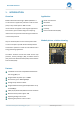
By default, this PIN is an empty feet. This PIN can connect to an external antenna to improve the Bluetooth
signal coverage.
If you need to use an external antenna, by modifying the module on the 0R resistance to block out the
on-board antenna; Or contact Feasycom for modification.
Note 6
This I / O port is shared with the internal SPI Flash chip. We do not recommend using this pin, floating
processing.
This pin is only available when the module is not equipped with air-upgrade function.
4. PHYSICAL INTERFACE
4.1 Power Supply
The transient response of the regulator is important. If the power rails of the module are supplied from an external
voltage source, the transient response of any regulator used should be 20μs or less. It is essential that the power rail
recovers quickly.
4.2 Reset
The module may be reset from several sources: Power-on Reset (POR), Low level on the nRESET Pin (nRST), Watchdog
time-out reset (WDT), Low voltage reset (LVR).
The RESET pin is an active low reset and is internally filtered using the internal low frequency clock oscillator. A reset will
be performed between 1.5 and 4.0ms following RESET being active. It is recommended that RESET be applied for a period
greater than 5ms.
4.3 General Purpose Analog IO
10-Bit ADC
Analog input voltage range: 0.4~1.4 or 0.4~2.4V based on configure
Up to eight single-end analog input channels
Two operating modes
◼ Single mode: A/D conversion is performed one time on a specified channel
◼ PWM sequence mode: When PWM trigger, two of three ADC channels from 0 to 2 will automatically convert
analog data in the sequence of channel [0,1] or channel[1,2] or channel[0,2] defined by MODESEL
(ADC_SEQCTL[3:2])
An A/D conversion can be started by
◼ Software write 1 to SWTRG bit
◼ External pin STADC
◼ PWM trigger with optional start delay period
Each Conversion result is held in data register with valid and overrun indicators
Conversion results can be compared with specified value and user can select whether to generate an interrupt
when conversion result matches the compare register setting
Channel 8 supports 2 input sources: External analog voltage and internal fixed band-gap voltage