INSTALLATION GUIDE Ceiling Projector mount MHP-100 Max Load Capacity: 50 lbs (23kg)
Note: Read entire instruction sheet before you start installation and assembly. WARNING Be sure to read this entire manual thoroughly and you fully understand all the instructions and warning before attempting to begin your installation. This product should only be installed by someone who has a basic knowledge of buiding construction,in stallations and fully understands these instructions.
Before you b egin, make sure all parts shown are included with your product. Parts may appear slightly different than illustrated. A Parts List Description A washer B C D E F G philips pan head screw philips pan head screw philips pan head screw philips pan head screw spacer L allen wrench allen wrench allen wrench allen cap screw concrete anchor hex bolt screw M M N N Hexagon fillister head screw nonskid nut Hexagon fillister head screw nonskid nut H I J K H M BB I N CC 4 Ø8.2x16x1.5 Ø8.
Installation to Wood Joist Finished Ceilings, Exposed Wood Joists, or Wood Beam Ceilings Drill four 1/4" (6 mm) dia. holes to a minimum depth of 1.57" (40 mm). Attach ceiling plate ( EE ) with four hex bolt screws M8x50 ( L ) as shown using 1/2" (13mm) socket wrench.Tighten wood screws ( L ). so ceiling plate (EE) is firmly attached. WARNING Tighten wood screws so that ceiling plate is firmly attached, but do not overtighten. Overtightening can damage the screws, greatly reducing their holding power.
Installation to Concrete Ceilings Drill four 3/8" (10 mm) dia. holes to a minimum depth of 1.57" (40 mm). Attach ceiling plate (EE ) using four concrete anchors (K) and M8x50 wood screws ( L ) as shown in Illustration A and 1, 2, and 3 (below). Tighten all fasteners. CONCRETE CEILING K WARNING EE L Tighten wood screws firmly, but do not overtighten. Overtightening can damage the bolt, greatly reducing its holding power.
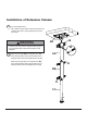
Installation of Extension Column Insert and tighten three M6 x 60mm hexagon fillister head screws (M) to lock adjuster tube (AA) to ceiling plate (EE) and lock it by nut (M). M EE WARNING Installer must verify that the ceiling will safely support the combined weight of all attached equipment and hardware. Slide extension pipe (BB) over adjuster tube ( AA) to the desired height. Attach with two M6 x 55 mm hexagon fillister head screws (N) and lock nut ( N ).
Removing the ceiling plate from the flush mount assembly Thumb tightening knob Spider-plate NOTE: loosen Thumb knob and slide spider-plate from ceiling mount. Pull out extension columns and install them to the projector 5 Loosen screws on spider arms. Place the Bottom Spacers in between the Extension Brackets and the Projector, and align the mounting. NOTE: Adjust spider arms to 4 mounting holes, install screws and firmly tighten. Be sure to maintain center balance point.
Install the bottom plate with projector to ceiling plate 6 CC J DD knobs. Insert and tighten one M4 x 3mm allen cap screw (J) to lock adjuster tube (CC) to ceiling plate (DD) .