Installation and User manual Digital Video Multiplexer/Recorder
Installation and user manual 2
Installation and user manual This page is intentionally left blank 3
Installation and user manual CE Information The product must be installed according to the currently valid installation regulations for EMC to guarantee the designed use and to prevent EMC problems.
Installation and user manual Contents SAFETY PRECAUTIONS ................................................................................................................................... 7 CONTENTS OF PACKING ................................................................................................................................. 8 FEATURES ........................................................................................................................................................... 9 .
Installation and user manual [ Alarm Out ]................................................................................................................................................... 53 SEARCH MENU ................................................................................................................................................. 54 1. SEARCHING VIDEO FOOTAGE .......................................................................................................................
Installation and user manual Safety Precautions Caution Before Use Please read this manual before installing or using the Vista Quantum DVR. Please keep this manual in a safe place, to allow for future reference For the safety and proper use, The DVR is marked with various symbols. Please read these to prevent injury of financial loss. Installation Site Ensure installation position is level, secure and adequately ventilated. Avoid installing close to sources of humidity or water.
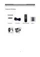
Installation and user manual Contents of Packing User Manual Mouse(option) Power Cable Remote Controller AC Adaptor 8 Battery
Installation and user manual Features ● Convenience - User-friendly GUI (Graphical User Interface) - Easy-to-use menu structure - Easy-to-use recorded data search (Time, Date, Motion, and Alarm) - Easy-to control via Front Panel, IR remote control and USB 2.0 mouse. ● Stability - Auto restart after power interruption DB structure offers data stabilisation and better storage utilisation ● Expandability - Remote DVR’s can be controlled using the supplied software client viewer.
Installation and user manual Rear Panel Connections ① ⑨ ⑩ ⑪ ② ③ ⑫ ⑬ ④ ⑭ (1) RS232 Serial Communication (2) AUDIO OUTPUT Audio output (3) COMPOSITE VIDEO OUT Composite Video Output (4) VIDEO IN 16 Camera inputs (1.
Installation and user manual (9) DC IN DC 12V 3.
Installation and user manual System Connection Diagram Camera e-sata HDD PC Client VGA Monitor Sensor Composite PTZ Monitor Camera 12 Keyboard Siren
Installation and user manual Alarm Connections The Alarm connections are made via the push in connectors on the rear on the unit. There are 16 individual alarm inputs marked as Sensor In (1-16) and 2 Outputs marked as Alarm, plus 2 ground connections.
Installation and user manual Remote Control 1. Power: Power ON/OFF 2. REC: Start & Stop Recording 3. (1 to 9) Numbers and letters 4. P/T/Z: Entering PTZ menu directly 5. OSD: On Screen Display ON/OFF 6. SEQ: Sequence operation 7. LOG: Direct access Log list 8. INFO: Direct access system Info. 9. ID: Reserved. 10.MUTE: Audio Mute 11.AUDIO: Switches through Audio channels 12. MENU: Entering system menu 13. SEARCH: Entering search 14. ARROW & SPLIT: Left, Right, Up and Down. Also, Screen split options 15.
Installation and user manual OSD Description PTZ icon Record Standby: It is shown when recording is not activated. The Status Bar shows HDD capacity, Network This screen shows PTZ control of connection, Time, etc using by icons. camera 2. The on screen arrows -HDD capacity will allow control of this camera. -Network connection : 1.7GB is used out of 298.0GB : It is shown that admin or user is connected.
Installation and user manual Menu Tree Main Menu Display Camera Setting Camera Covert Camera Name Spot Setting OSD Setting Live Setting Recording Global Watermark Frame HDD Overwrite Event Audio Action Pre-Alarm Duration Schedule Holiday Time Duration System Basic Language Disk Auto Delete Mode Account Date Format Program Update Time/DST Set Sensor Video Type PTZ Setup System ID PTZ Controller 16
Installation and user manual Network DDNS IP SET NTP Live Event E-Mail Registration SMTP Mode E-Mail Out Beep Out Alarm Out Search Date/Time Search Event Calendar Archive All Power Log Record Operation Client Event Archive 17 DDNS User ID User Password Domain Dynamic IP IP Gate Way Net Mask DNS Server DSL ID DSL PW DVR Port Web Port
Installation and user manual Default Passwords Front Panel A Password is required if you need to: Log on; enter the menus; down power; stop recording or changing an IP setting. Logging ON Before the system can be used it is necessary to Log On as a user, he rights of each user can be managed by an administrator level log on Press MENU on the front panel, or right click and select the MENU icon. The following box will be displayed played asking for password.
Installation and user manual Click on arrow to view a quick connection address book for the last 22 units that the software has been connected to. This uses the description to quickly identify each unit. Menu Navigation To enter the set-up menus, the user has to have the required access rights and be logged on press the Menu button or right click with mouse on screen and select the menu icon. The following screen will be displayed.
Installation and user manual Note: This display is also used to select Search mode, Turn on the telemetry mode.
Installation and user manual If Menu has been selected the following screen will be displayed. Select Sub menus by clicking on the relevant title. The method of altering the value of a segment within a menu page will vary slightly depending on the page: 1. Clicking on a segment will toggle through available values 2. Click on icon at top of list will change all channel values 3.
Installation and user manual Menu Settings 1. Display [ Camera Setting ] Brightness, Saturation, Contrast, Hue and default The picture displayed from each camera can be individually adjusted to balance the multi screen view. Use UP( ) / DOWN( ) keys to select the cell to be altered, then press select to turn the box green, then use the numeric keys to change the values.
Installation and user manual numeric keys to select the character ( Similar to SMS on a mobile phone). When complete press the select key to exit. Alternatively use the mouse to select the title to alter, the on screen keyboard will appear, enter the title followed by the OK button. [ Spot Setting ] <9 Channel Divisions> <16 Channel Divisions> Spot output is used to configure the second monitor output.
Installation and user manual [ OSD Setting ] Selecting how long the graphic information is displayed on the screen. Status Bar The display bar at the bottom of the screen can be set to be permanently on or to disappear after a period of time.
Installation and user manual [ Live Setting ] The live settings are used to set up a sequence of either full screen camera images or multi screen displays Use the Up and Down arrows to select either: Full Screen, Quad or Nine way split sequences. The display will change to allow individual sequence times to be set per channel or split screen option. Use the select key to turn the cell green and then the Up and Down keys to change the values.
Installation and user manual 2. Recording [ Global ] Watermark Generally this should be set to on, this allows the supplied software to verify the downloaded information to ensure it has not been tampered with or changed. HDD Overwrite Generally this should be set to on to ensure that the DVR does not stop recording when the hard drives are full. Audio Enable each audio channel for global recording.
Installation and user manual be set to 0, 5, 10, 15 or 20 seconds [ Frame ] This configures the FPS for each schedule – Day/ Night/ Weekend & Holiday/ Time/ Instant recording. ⑥ ⑦ ⑧ ⑨ ⑩ ⑪ ⑫ ① ② ③ ④ ⑤ In Schedule Setup, users can define the recording schedule : ① Day ② Night ③ Weekend/Holiday ④ Time ⑤ Instant Recording Configure the FPS for each schedule – Day / Night / Week(Holiday) / Time / Instant ⑥ Resolution Each channel can be individually configured for record rate.
Installation and user manual ⑦ Recording mode : [C] / [E] / [C+E] / [N/A] C : Continuous , E : Event , C+E : Continuous + Event ⑧ Continuous Recording FPS NTSC : 0~30fps , PAL : 0~25fps ⑨ Event Recording FPS NTSC : 0~30fps , PAL : 0~25fps ⑩ Audio recording Enable each audio channel for recording. ⑪ Post recording 10 ~ 99 sec ⑫ Quality Best / Good / Standard [ Event ] When an event comes in the DVR records he image according to its settings(Frame menu) and triggers an alarm(Action).
Installation and user manual ③ Motion Area Define the motion detection area. To setup the motion detection grid per channel select the “Sel” button The detection area is divided into a grid of 11x9(PAL) / 11x8(NTSC) cells. Default is all cells in active mode. Use the Left/ right/ up/ down btton to move cursor and the Select key to toggle between active and inactive. The mouse can also be used to select cells and toggle them on and off. Care must be taken in setting of the motion sensitivity.
Installation and user manual ① Channel ▲ Channel 1~8 ▼ Channel 9~16 ② Relay On/Off Associate an alarm relay with a channel. ③ Preset on Alarm Enable PTZ camera to move to a preset position when an event occurs. See PTZ control for more information. A single alarm input can be used to drive up to 4 PTZ cameras to preset positions or Preset tours. [ Schedule ] ① Night Set night time. Ex. If 18:00 to 6:00 is defined as night time, 6:00 to 18:00 is defined as daytime.
Installation and user manual ② Weekend Define weekend. [ Holiday ] Define Holiday (1) Press ADD button. ① ② ③ ④ ⑤ (2) Define holiday pressing the buttons. ① Select day or date ② Month ③ Ordinal ④ Day ⑤ Duration (3) Press OK button when finished setting the holiday.
Installation and user manual [ Time ] The time recording allows the DVR to be set to only record at particular times of the day. (1) Press ADD button. ① ② ③ ④ (2) Set the recording time pressing the buttons. ① Day ② Start Time ③ End Time ④ Channel (3) Press OK button when finished setting the recording time. (4) Repeat the above steps to set up more recording times. (5) Press APPLY to save settings.
Installation and user manual The resolution; whether cameras are active or not and whether audio is being recorded can each be set per channel. The user then sets the number of days of recording required, then the E4000 will automatically calculate best record rate to achieve these settings ① ② ③ ④ ⑤ ⑥ ⑦ ① Channel ▲ Channel 1~8 ▼ Channel 9~16 ② Resolution Each channel can be individually configured for record rate.
Installation and user manual 3. System [ Basic ] User can set Language, Auto Delete Mode, Date Format, Time/DST Set, Video Type, System ID. Also, Initialisation and system Information is available. Language The default is English. Italian, French, Hungarian, Slovak, German, Russian, Chinese, Dutch, Spanish, Portuguese, Japanese Danish and Polish are available. Auto Delete Mode Auto Delete Mode can be set to automatically erase recorded older than a certain number of days.
Installation and user manual Time/DST Setting The DVRs time can be set by clicking on the time and date displayed in this section, the on screen keyboard will appear. Set the time and date and click Ok, next select the country to enable the Day Light Saving mode. If the country does not appear in the list the use the User define option as shown below: PLAYBACK FOLLOWING TIME CHANGE The DVR uses the time and date to index video on the hard disk drive so you can find it later.
Installation and user manual Video Type Video Type can set in this menu without rebooting or initialisation. The default is PAL, NTSC can also be selected System ID The remote control can be used to control up to 16 DVRs, the ID number on each can be set to a unique address so that the remote will only control one at a time if they are in close proximity. The default is 11. Repeated click on the ID value to change to the required number.
Installation and user manual [ Disk ] Format Formatting of the drive is used when new drives are installed or you need to wipe all information on the disk. Click on OFF to turn to ON, then click on Execute, click YES, to confirm Smart This function is used to keep a check on the health of the Hard disk. The parameters which can be monitored are: 1. Read/Write errors on the drive 2. Drive temperature.
Installation and user manual [ Account ] The DVR can have the following different levels of operators, each with different users rights and passwords: Admin level – Manager level – Users 1-4 - Operators logged in at this level has full rights Operators logged in that this level as default have access to all except: Stopping Recording and Shutting down the DVR. Operators logged in at this level Only have the ability to Search and play, Control PTZ cameras and get access via the network.
Installation and user manual Automatic timed log out The system can be set to automatically log out a user after a certain amount of time if no key presses have been made. The operator level has to have been activated before this can be set. While in the account setup page for the User, click on the middle icon at the bottom of the menu page , the screen will change to show the following: Click on the boxes adjacent to “Local” for the time out period for operation form the front panel.
Installation and user manual [ Program Update ] Always turn off : Playback and Network access while upgrading the unit The latest firmware version can be upgraded through USB 2.0 Port using Memory Stick or CD/DVD Media. When a memory stick is connected to the USB port, this symbol be shown in the status bar of the screen. will Enter “menu”-> “System Set”-> “Program Update”. If the system recognizes the new firmware then, “New program found” will be displayed on the screen.
Installation and user manual [ Sensor ] The 16 alarm inputs on the rear of the Quantum can be configured to be normally open (N.O), normally closed (N.C) or None. [ PTZ Setup ] The E4000 DVR can control PTZ cameras via coax or a RS485 connection on the rear of the DVR. The cameras can have individually selectable Protocols with a choice of Pelco P or Pelco D etc. The Baud rate can also be selected.
Installation and user manual [ PTZ Controller ] The E4000 DVR needs to be setup to accept the VKBD3im, VKBD4 or QSC1000 keyboard, as a default this will be set to the correct Protocol and Baud rate, the ID RS485 Address my need to be adjusted dependant on the number of PTZ cameras on the system. The Keyboard ID should not be the same as any of the domes on the system.
Installation and user manual Telemetry connections and User Instructions Remote Keyboard Connections The connection of the keyboard to the E4000 DVR, is made via the push connectors marked as Kbd on the rear of the DVR, These is the 2nd connector to the left hand side of the bank of push in connectors. RS485 Dome Telemetry connections The connection to RS485 domes is made via the push connectors marked as Tel on the rear of the DVR. The domes can be wired in a Daisy chain, examples shown below.
Installation and user manual PTZ user instructions The telemetry function of the Quantum Plus can be controlled via 3 different methods: 1. Remote keyboard 2. Remote control 3. Software viewer Remote Keyboard : See keyboard manual for control of PTZ cameras Remote control functions [ Camera selection ] The PTZ cameras can be controlled in either full screen or split screen mode.
Installation and user manual 2. To recall a Preset Press the search key followed by the number (1 -9). [ Run Tour 1 ] To run Tour 1, press the search key followed by the number 0 (Zero). The tour requires a keyboard to set it up in the domes menu. Dome Menu access When controlling PTZ domes from the E4000 DVR, it is possible to enter the Dome’s menu structure, using the Remote Keyboard, Mouse or the Client software.
Installation and user manual 6. Click On the word 7. The Dome Password Menu will appear 8. Using the Arrows enter the Domes password, 9. Once in the Menus use the arrows to navigate. 10. To Exit repeatedly press ESC 11. To remove the navigation arrows, right click. Client Software 1. While Client software is running select the dome required. 2. Enter Pan and tilt mode by clicking on the icon 3. The Pan and tilt control window will appear 4. Click on the central button 5. The following box will appear 6.
Installation and user manual 4. Network (If the DVR is connected to a network, this icon will be shown in the OSD display) This menu can only be accessed if the user has the necessary rights. (Default password is 00000000). With in the Network menu the DDNS (Dynamic Domain Named Server), IP addresses, NTP and Live can be set. [ DDNS ] What is DDNS? DDNS is a service that maps Internet domain names to IP addresses.
Installation and user manual [ IP SET ] When a fixed IP address is being used, the Use Dynamic IP should be set to NO The IP Address, Gateway and Subnet Mask need to be set, these will generally be given by the Network Manager. DSL refers to all types of Digital Subscriber Line such as ADSL and SDSL. The DVR Port and WEB Port can both be changed if required, default are 2000, and 80 respectively. [ NTP ] The Network Time Protocol Setting allows the DVR time to be synchronised with an external time server.
Installation and user manual The Time zone can also be chosen within the City selection, use the right arrow on the front panel to change the city settings. [ LIVE ] This allows a separate Live viewing resolution and Quality, regardless of System Recording and Quality, to be set for remote viewing, this helps optimise the network streaming.
Installation and user manual 5. Event This section is used to inform the user as to an event occurring, this can be by the sounding of a buzzer or by sending an E-mail to a predefined address. [ E-Mail Registration ] Within this section up to 3 users can be set-up to receive an email on the occurrence of an event such as Video Loss / Alarm / Motion or Power Loss. An E-mail will only be sent if the E4000 is sitting on a network with access to the Internet, e.g. through a router.
Installation and user manual [ SMTP Mode ] The SMTP (Simple Mail Transfer Protocol) function allows e-mails to be sent over a LAN The default is SMTP Mode “OFF”. In order to activate SMTP Mode, choose SMTP Mode either IP or Domain first. Then, put ID, Password, IP address, and port. Finally press “SMTP Status Check” to test.
Installation and user manual [ E-mail Out ] As well as e-mail on event activations the E4000 can be set to send a report on the following occurrences: Video Loss; Alarm; Motion: Power Loss and Smart (Hard disk monitoring). [ Beep Out ] The buzzer can be set to sound on the following occurrences: Video Loss; Alarm input; Motion detection; Power Loss; Smart (Hard disk monitoring). The duration of the beep can be set.
Installation and user manual [ Alarm Out ] The Alarm out relay can be set to activate on the following occurrences: Video Loss; Alarm input; Motion detection; Power Loss; Smart (Hard disk monitoring). The duration of the activation can be set.
Installation and user manual Search Menu 1. Searching Video Footage To access the search option, press the SEARCH button on the front panel or right click the mouse and select Search, (A password may have to be entered) after which the following screen will be displayed. [ Date / Time Search ] If you select date/time search, the following will be shown. Use the numerical number on the front panel or the mouse to select the time and date required, then select Play.
Installation and user manual [ Calendar Search ] Following screen is displayed when “Calendar” search is selected. The Calendar search gives a graphical representation of when video is recorded on the hard drive. The year and month can be selected. This month is shown as a calendar on the screen, any day which contains recorded video will be indicated by a highlighted number in white. Move to the desired day by using the up / down / left / right buttons, Select the day by pressing SEL.
Installation and user manual The hours which have recorded data are displayed as a coloured bar. Select the hour which you want to review, the following screen will be displayed. Minutes hour in the The minutes which have recorded data will be displayed as a coloured bar, click on the time required; the recorded data will be played back from this point.
Installation and user manual 2. Archiving Evidence to DVD/CD or USB Once the required video has been found, it may be necessary to down load it for evidential purposes. This can be done either onto the internal CD/DVD-R writer or via the USB port on the front of the E4000. To do this press the SEARCH button and using the down button move to ARCHIVE, once highlighted press SEL, the following screen will be displayed.
Installation and user manual Channel As long as the EXCLUSIVE file format is selected, the number of channels to be down loaded can be selected. Anything from a single channel to all 16 can be selected. Calculate Archive size Once the time and date and file format have been entered, it is necessary to confirm that the size of file created will not exceed the size of memory available on the disk or USB device. Move to Calculated Archive size and press SEL.
Installation and user manual 3. Log The log file contains information on the following: Power: Record: Operation: Client: Event: Archive: Power on, Power off, Power fail Rec fail, Rec start, Rec stop, Rec error, Rec full Play start, Play stop, HDD format, Menu set R_Login, R_Logout, R_Logfail, R_Play, R_Transfer, R_Rec on, R_Rec off, R_Upgrade Alarm, Motion, Audio, Video loss, Email fail This lists the USER, time/date when Archive was done, and time range of archived section.
Installation and user manual Client Viewer software Each E4000 comes with license free viewer software to view the E4000 across a network. To be able to do this the recommended minimum specification for the PC is as follows: Minimum PC specification > CPU: Core 2 Duo 1.8GHz, > Graphic Memory: 256MB Installing software When you put Quantum Network installation CD into your PC, it will auto run and lead you through an installation wizard. Follow the instructions.
Installation and user manual Logging on The following window will appear. To connect to the E4000, enter the units: IP address; DVR Port (2000 ids default), ID and Password. Then, click “OK”, to start the live monitoring. Description field is the name of area / Building / location of the DVR, this should be typed in he first time the unit is connected to, this will store it in the address book. Address book Click on the Arrow to the left of the IP address, the following box will appear.
Installation and user manual Explanation of Screen Buttons 62
Installation and user manual Live Monitoring The software is best viewed with the PC monitor resolution, set to: 1024 x 768. Split Screen options (1, 4, 6, 7, 8, 9, 10, 13,16): Spilt Screens can be viewed during both live and playback. The splits screens available are: full screen,4,6,7, 8,9,10,13 and 16 way.
Installation and user manual Full Screen on/ off When the full screen button is selected, a tool bar offering the various split screen options, and the Exit key will be displayed at the bottom of the screen. OSD on/off: The OSD button will toggle between the on screen titles etc being shown or hidden (Smart) Arrange On/Off: If Cameras are being displayed in segments that are not logical, the Smart button will rearrange and put camera input 1 into segment 1 (Top Left) etc.
Installation and user manual Image Save / Load: / SAVE: This icon is used to save a still image in either JPEG or BMP or TIF format. There is no change on the main screen when the “Save” icon is pressed. The still image is stored as default in C: H264CD: Saved folder, as a Jpeg image using the date and time as the file name. LOAD: This icon is used to retrieve and view a saved still image, when selected a list of available images will be shown.
Installation and user manual Remote search Search (Date/Time/Event/Calendar), Archive (Remote Archive), Log (Remote Log) are available. SEARCH This Remote Search is able to play back video on the PC direct from the hard disk storage on the Quantum Plus. There are 3 options for as follows. 1) Date/Time 2) Event 3) Calendar Date/Time When the cursor is placed over a part of the time and date a drop down arrow will appear, use this to set the required value. When set.
Installation and user manual Calendar Select the date required (as long as the date is highlighted in Blue there is recorded data on from that day). There are 3 options for selecting the required time once the date has been selected. 1) Drag the Red line along the colour bar (I.e. Blue: Normal Recording) till the required time is reached. 2) Click on the required time for playback on the blue bar then the red line will move to this point.
Installation and user manual Select Channel: Channels can be included or excluded dependent on query. This is available within Search, Backup and Logs. . ARCHIVE Remote Archive – Date/Time Enter the Start and End dates and times, by hovering over the selections, a drop down box will appear. Once selection is made, then “click” calculate, the file size will be displayed. Finally click “Archive”, the file will be transferred to C:\ H264CD \Download.
Installation and user manual Remote Archive – Calendar Select the date required (Days with recorded video a data present are highlighted in Blue) There are 3 options for selecting the required time once the date has been selected. 1) Drag the Red line along the colour bar (I.e. Blue: Normal Recording) till the required time is reached. 2) Click on the required time for playback on the blue bar then the red line will move to this point.
Installation and user manual The backup procedure is same as Date/Time & Event backup as previous page. * “Prev” to go back to previous stage. *The downloaded data is saved in the follows location. C:\H264CD\Download. Play back down loaded files Open the viewer software but do not connect to a unit, click the cancel button to remove the log on box.
Installation and user manual Remote Log The Log file can either be viewed or printed. The recorded Event can be played, by selecting it and clicking on Play.
Installation and user manual Remote Setup: (Menu settings - Same as DVR) 1. Display Camera Setting Within this setting the Hue, Saturation, Contrast and Brightness can be adjusted on a camera by camera basis. Camera Covert Cameras can be remotely set into Covert Mode, they are still being recorded but cannot be viewed local to the system, or by any remote user apart from the Administrator on line.
Installation and user manual Camera Name Up to 32 Characters are available for each camera name. Spot Monitor settings 1) Set “Mode” (normal screen or Event). 2) Next select Duration for a sequence.
Installation and user manual OSD On/Off Selecting how long the graphic information is displayed on the screen.
Installation and user manual 2. Recording 1. Watermark – security tagging of recorded video. 2. HDD Overwrite – When the disk is full it will overwrite the oldest data. 3. The Picture quality can be set 4. Alarm mode can be set between Exclusive and Normal 5. Non- Alarmed resolution – this is the resolution that non alarmed cameras are recorded in during an alarm event 6. Non-Alarmed FPS- this is the rate that non alarmed cameras are recorded in during an alarm event 7.
Installation and user manual Event When an event comes in the DVR records he image according to its settings(Frame menu) and triggers an alarm(Action). Action Associate an alarm relay with a channel and enable PTZ camera to move to a preset position when an event occurs.
Installation and user manual Schedule Set night time and define weekend. Holiday Define holiday.
Installation and user manual Time The time recording allows the DVR to be set to only record at particular times of the day. Duration The Duration mode allows the user to set the number of days that they require to record for.
Installation and user manual 3. System Basic This section is used to select: Language Date format Video type System ID Live viewing resolution – over the network Live Quality – over the network DST Setup (Daylight Saving Time) The E4000 can be set to automatically reset its clock when the clocks change for Day Light Saving time. As default this is set to Off. User Define : Change “Off” to User Define, this will allow the exact date and time for the change to occur.
Installation and user manual Account Editing ID & password The E4000 allows for : 1 Administrator level log on 1 Manger level log on 25 User level log on Each of the 27 log-on accounts can be given individual passwords and user rights. User rights can be applied. Auto Log out After a certain amount of time (15mins, 30mins or 1 hour) of inactivity.
Installation and user manual Sensor Each of the 16 alarm inputs can be configured to be either inactive (NONE), or Normally Open (N.O), or Normally Closed (N.C). PTZ Setup ID Each camera input can be allocated an RS485 ID between 1 and 255. Protocol Each camera output can have individual protocol associated with it.
Installation and user manual PTZ Controller Each Keyboard can be allocated an RS485 ID between 1 and 255. Each keyboard can have an RS485 protocol associated with it. 4. Network NTP NTP setup allows the DVR to have its internal clock synchronised with an External clock. The default setting is “Off” Type allows selection between: Default – Time server is “time.bora.net”. Domain – Where another time server name can be added. IP – Where an IP address for a time server can be input.
Installation and user manual 5. Event E-mail Registration The E4000 will send E-mails to up to 3 defined addresses under certain conditions such as Alarms or video loss. The screen is where you setup the receiving address and address that the DVR will send from. The mails can be set to be sent immediately an event occurs, Daily or Weekly. E-mail Out The actions which cause an e-mail response can be defined within this screen.
Installation and user manual Beep Out The internal buzzer can be set to sound on the following occurrences: Alarm activation Motion Detection Video Loss Power loss The duration of the buzzer can be set. Alarm Out The Alarm output relay can be set to activate on the following occurrences: Video Loss Alarm activation Motion Detection Power loss The duration of the relay closure can be set.
Installation and user manual Local Search (viewing downloaded footage) This allows playback of video which has been downloaded top the PC. Search Searches can be done by Date/Time, Even and Calendar. Date/Time Hovering over the Date and Time bars will allow drop down boxes to select the required time and Date. Once set, click Play. Event Choose the Event search box then choose the type of Event you are searching for, options are: Alarms, Motion or Audio.
Installation and user manual Calendar When the Calendar option is chosen this screen will appear, any day with recording available will be highlighted in Blue. Select the required day. Any downloaded event s will be shown, click on the event, the red line will move to that event. Then click Play to review the recording.
Installation and user manual Log Clicking on Log will display the log file from the unit. This file can be printed, by clicking Print. Info Click on Info. This will display the version of the software client being used.
Installation and user manual Local Setup This allows the setup of the viewing of the software on the PC. Global This screen allows the following: Draw mode to be set to YUV or RGB Date Format to be set to: DD/MM/YYY, MM/DD/YYYY or YYYY/MM/DD. Save Format, for the saving of stills as either JPEG, Bit Map or TIF. Location for where stills are saved. Opacity The opacity or “boldness” of the OSD can be individually set per function. The lower the number the more see through the box.
Installation and user manual Audio Buffer Audio Buffer settings are there to adjust the audio over the network, this will compensate for different network speeds ( LANs, WANs etc). This can only be adjusted if the LIVE video is switched off. Adjust each variable to achieve best quality video for Network bandwidth available, this is best done through trial and error.
Installation and user manual PAN, TILT, Zoom, Focus (Remote telemetry control) When PTZ button is being pressed, PTZ control icon will be pop-up on the live image. PAN/TILT/ZOOM/FOCUS When PAN/TILT button is clicked the Pan/Tilt control appears, this allows Left, Right, Up and Down Control of PTZ When Zoom/Focus button is clicked, the control changes to Zoom in on the up arrow, Zoom out on the down arrow. Focus near on the left button and focus far on the right arrow.
Installation and user manual PRESET/LEARN PRESET&LEARN icon The presets button can be activated by clicking on the centre of the control icon, the preset symbol will appear and the Preset selection box will appear. To save a preset, move the camera to the desired position then click “Set” followed by the desired number. To recall the preset, click “Call” followed by the desired number.
Installation and user manual Firmware Upgrade User can select Firmware Upgrade menu, if a new version of firmaware exits in the C:/H264CD/Upgrade folder ,then the message ‘New program found!’ will be displayed if there is no file then ‘New program not found!’ message will be displayed. To proceed with upgrading press the OK button and select each firmware files to upgrade it to the system, by ticking the boxes. Once the upgrade has been completed the following message will appear.
Installation and user manual Appendix 1 Alarm Sensor Installation 1. Components 1) External Sensor : 1 2) DVR System : 1 2.
Installation and user manual Absolute Maximum Ratings Parameter Forward current *1Peak forward current Input Reverse voltage Power dissipation Collector-emitter voltage Emitter-collector voltage Output Collector current Collector power dissipation Total power dissipation *2Isolation voltage Symbol IF I FM VR P V CEO V ECO IC Rating 50 1 6 70 35 6 50 Unit mA A V mW V V mA PC 150 mW P tot V iso 200 5 000 -30 to + 100 -55 to + 125 260 mW V rms Operating temperature T opr Storage temperature T s
Installation and user manual 3. SENSOR Install Processing ① Please refer the below block diagram.
Installation and user manual Appendix 2 Dynamic IP (Supporting DDNS Server) With DDNS Server, This allows a user to connect to the unit remotely without the need for a fixed IP address.(Please register your ID & Domain at www.ddns-dvr.com in which you can use their DDNS server as free of charge) 1. Visit www.ddns-dvr.com to get the DDNS user ID & PW as well as Host name. 2. Click to create / set account of “Dynamic DNS”. 3. Select “Create Account” menu.
Installation and user manual 4. Create Account. Fill in all blanks in order to create new account. ID & Password will be emailed to you when the account is setup correctly. Once the DDns-Dvr account has been setup, it is necessary to add the details in the Network section of the E4000’s menus. DDNS SET To enter Network set menu, system ask password (Default is 00000000). In DDNS environment, need to be changed DVR & Web server port, please refer to IP set. Set up DDNS 1. Change DDNS to ON 2.
Installation and user manual Appendix 3 Setup For DVR Port/ Web Server Port Using IP Sharing Router (Port Forwarding) 1) To use IP sharing router, “Dynamic IP” should be set to “NO”. - DVR Port : This can be set to any number between 2000 to 65535. - Web Server Port : This can be set to any number between 2000~65535, as long as it is not the same as the DVR Port number. 2) Setup “virtual server” on IP sharing Router It is for setting virtual server to forward IP which is allotted to DVR.
Installation and user manual Appendix 4 Specification Model Camera Input(NTSC,PAL) Output Audio Input Audio Output Sensor In / Alarm Out Operating System VGA Resolution Display BNC Resolution Split Screen Compression Resolution(Pixel) Picture Quality Mode Recording NTSC Speed Total PAL Video Playback Network Archive Display Search Mode Speed Device Network Interface Protocol Serial Communication Web Browser Event Transport Viewing Interface Archive Device Motion Detection Control Others Alarm Hold T
Installation and user manual Subject to change without notice 100