User’s Manual Powerline 200M Ethernet Bridge
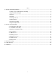
Index 1. Powerline Networking Installation.............................................................................................................................2 1.1 Simple step to install Powerline Networking .........................................................................................2 1.2 Application Block Diagram ....................................................................................................................3 1.3 Benefits............................................
1. Powerline Networking Installation 1.
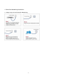
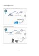
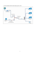
1.2 Application Block Diagram 1.2.1 Internet ADSL with one computer via power outlet 1.2.
1.2.
1.3 Benefits ‧Data transfers at up to 200 Mbps over the household power circuit ‧Ranges of 200 meters ‧No need new wires for Home networking ‧Deliver the benefits of Ethernet without the wiring expense ‧Send even large files between PCs without long waits ‧High-speed Internet and DVD-quality video streaming ‧Fully compliant with IEEE 802.3, IEEE 802.3u ‧Privacy through DES encryption 1.
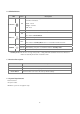
1.6 LED Definitions LED State Description Powerline network activity. Powerline Link Status; Powerline ON Green – Good Orange – Normal Red – Poor OFF ON Ethernet Ethernet connection is OK. Auto switch to Normal Mode. Flashing Data transferring. OFF ON POWER Search or no Powerline network activity. No Ethernet link. *Auto switch to Standby Mode after 2 second while No Ethernet Link. Power on. Flashing *Auto flashing every 0.5 second when switch to Standby mode. OFF Powerline off or failure.
2. Powerline Networking Utility Note. The Powerline Device can auto detect the other powerline bridges which plug in the same power circuit, you don’t need to use this powerline utility except you want to encryption all the powerline devices as the same group or you can not access the other computers.
Figure 1: Install Shield Screen 8
2.2 Windows Configuration Utility In order to run the utility, double-click the utility icon. Figure 2 shows the main screen of the configuration utility. This screen shot shows a Powerline Ethernet device connected as a local device and other Powerline Ethernet devices as remote devices.
2.3 User Interface 2.3.1 Main Screen The Main screen essentially provides a list of all Powerline Ethernet devices logically connected to the computer where the utility is running. The top panel shows all local Powerline Ethernet devices found connected to the computer's NIC (Network Interface Card). In most cases, only one device will be seen.
The lower panel displays all the Powerline Ethernet devices, discovered on the current logical network (remote devices). Displayed immediately above this panel is the number of remote devices found, the type of logical network (Public or Private), and a message area that reports connectivity and scan status. The following information is displayed for each of the devices discovered that appear in the lower panel: Device Name column shows the default device name, which may be user re-defined.
The Add button is used to add a remote device to your network that is not on the displayed list in the lower panel, for example, a device currently on another logical network. Users are advised to locate the passwords for all devices they wish to manage and add them to the local logical network by clicking on the Add button. A dialog box will appear as seen below. The dialog box allows the user to enter both a device name and the password.
The Scan button is used to perform an immediate search of the Powerline Ethernet devices connected to the computer. By default the utility automatically scans every few seconds and updates the display. A typical screen after naming and supplying passwords might appear as in Figure 6.
2.3.2 Privacy Screen The Privacy dialog screen provides a means for managing the local network and providing additional security. All Powerline Ethernet devices are shipped using a default logical network (network name), which is normally “HomePlug”. The Privacy dialog screen allows user to make the network private by changing the network name (network password) of devices.
The Set Local Device Only button is used to change the network name (network password) for the local device only. After doing this, all the devices seen on the Main panel prior to this will no longer be able to communicate or respond to the computer, as they will be on a different logical network. Devices previously set up with the same logical network (same network name) will appear in the device list afterward selecting this option.
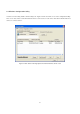
2.4 Diagnostics Screen The Diagnostics screen shows system information and a history of all devices seen. The appearance is shown in Figure 8. The upper panel shows technical data concerning software and hardware on the host computer used to communicate over Powerline Ethernet Network.
The lower panel contains a history of all remote devices seen on the computer, over time. Devices are shown here regardless of whether or not they are on the same logical network. Devices that are active on the current logical network will show a transfer rate in the Rate column; devices on other networks, or devices that may no longer exist are shown with an “?” in the Rate column.
2.4.1 About Screen The screen shows the software release date. Figure 9: About dialog screen 2.4.2 Preferences The lower part of the panel may display options for user preferences (such as turning the auto-scan feature on or off) as shown Figure 9 above.
3. Push Button Setting There are 2 buttons in this device, one is Reset button the other is Secure button. Reset: Push this button can reset to the factory default settings. Be careful, when you press the reset button, please make sure unplug (remove) the Ethernet cable (RJ-45cable) first, and then press the reset button. After press the reset button (the time need < 3 sec) and then wait the PWR LED light again. Don’t power off when the device is in reset process.
Possible Use Case Scenario 1: Unassociated device joining existing AVLN Possible Use Case Scenario 2: Two devices joining to form new AVLN Before this scenario begin, please make sure to press each device secure button > 10 sec till all LEDs re-flash to generate the random network password key first.
Possible Use Case Scenario 3: Reset 21
4. Trouble Shooting 1. Why my utility can not work properly after finish install steps? Ans: Please follow the steps to check the problem. 1. Check the Windows version, the utility only can support windows 2000, XP, 2003, vista 32, Vista 64. 2. Reinstall the utility again, you can remove it and reinstall the utility again. 3. If the OS is vista 64, make sure you install the correct utility for vista 64. You can see it in CD auto run utility page. 2.
5. Certification Declaration of Conformity The following Equipment : Power Line 200M Ethernet Bridge Report No.