STANDALONE H.
Before usage The User manual is for DVR installation and operation. The user who install the device first or Qualified Personnel, before installing DVR, has to read user manual carefully and follow warning instructions avoiding malfunction of operation or product failure. Refer all servicing to qualified service personnel or suppliers while install and set the DVR. Keep these operation instructions handy for future reference.
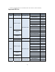
ㆍ Contact to Supplier after turn off the DVR, when odor smoke or smell in the DVR, Approved HDD list Capacity Manufacturer HDD Model 160G Western Digital HDD 160G SATA F/W Ver.
HDD 1TB SATA WD10EACS HDD 1TB SATA WD10EADS-00L5B1 HDD 1TB SATA WD10EARS 00Y5B1 HDD 1TB SATA WD10EADS 00L5B1 HDD 1TB SATA ST31000528AS CC38 HDD 1TB SATA ST31000322CS HDD 1TB SATA HCS5C1010CLA382 HDD 1TB SATA HDS721010CLA332 HDD 1.5TB SATA ST31500341AS HDD 1.5TB SATA ST31500341AS CC1N HDD 1.5TB SATA WD15EADS 00R6B0 HDD 1.
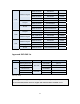
- Contents - 1. Overview ∙ Feature ……………………………………………………………………………………………………………………………………..……….8 ∙ Application ………..………………………………………………………………………………….……………………..…………………….8 2. Installation ∙ Package contents ……………..……………………………………………………………………..………………………………………..9 ∙ Rear panel ………..….……………….………………………………….…………………………….………………………………………..10 ∙ Video Input ………………..…………………………………………………………………………...……………………………..………..11 ∙ Loop out ………………………………………………………………………………………………..….…………………………………….11 ∙ VGA output ………………….
∙ Log out ………..………….………………………………………………………………………………………………….……………..…….29 ∙ Serial Port set-up(RS-485) ……….………………………………………………………………...………………………..……..…..29 5. Display ∙ OSD …………………………………………………………………………......................................................................................…..30 ∙ Split mode ……………………………………………………………………………………………………………………………..…...…..30 ∙ Auto Sequence …………………..……………….………………………………………………………………………………..………...34 ∙ Display control ………………….………………….………………………………………………………………………………..……….35 6.
∙ How to control Playback …………………......…………..…………………………………………………………………….………59 11. Back up …………………………………...……………………………………………………………………….……….……………...…61 12. Appendix ∙ Specification ……………..……………………….……….………………………………………………………………….............….…..63 ∙ Product Warranty ………………………………………………………………………………………….….………..…………….…..
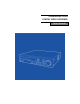
Chapter 1. Overview Feature The DVR employs H.264 video recording 4ch, 9ch, 16ch channel input and S-VHS and Spot out put simultaneously. The DVR has mirroring function, mirroring HAD record and display regardless of unexpected physical shock or damage.
Chapter 2. Installation Package contents HDD screws (10 EA) Software CD Controller battery Size: AAA 1.5V X 2EA User manual DIGITAL VIDEO RECORD Adaptor (12V 6A (SMPS) Power code Remote controller Package contents are consist of as followings. √ Digital Video Record (1EA) √ HDD screws (10 EA) √ Software CD (1EA) √ User Manual (1EA) √ Power code (1EA) √ Remote Controller (1EA) √ Controller Battery AAA (1.5V 2EA) √ Adaptor (12V 6A 1EA) [Note] Make sure Package contents when you purchase system.
Rear panel It doesn’t need specific equipment to install DVR. Refer to each parts explanation in user manual.
Video input Connect Coaxial cable from Video source to BNC Video in connector. Loop Out (Video source output) Used to transfer a video signal to other video devices. VGA Output Use VGA input type of LCD monitor and CRT monitor.
RS-485 Connect (PTZ Camera) PTZ Camera Before connecting PTZ, check PTZ Protocol whether compatible protocol or not in DVR, if it is, connect cables as configuration. RS-485 Connection (External Keyboard Connection) or The DVR is controlled by specific keyboard, please ask supplier to purchase keyboard. You can find Keyboard installation in keyboard user manual. [Note] The user controls DVR through Keyboard or external devices such as PC, 99pcs of DVR is controlled by provided DVR protocol.
Alarm output connection Support 1 alarm output, connect cable same as above. [Note] Provides simple On/Off switching by using relay Sensor input connection Provide 4 Sensors, connect sensor same as above.
RJ-45 Port (Internet connection) Connect network through 10/100/1000Mb Ethernet connector. Available remote surveillance and remote search by network between DVR and computer. . USB port Support 2 USB ports in the front panel, it uses for Firmware upgrade, back up, Mouse. Call menu Available Menu set-up through Menu button in front panel, mouse and Remote controller. Keep in mind of user manual to overall set up system. ∙ Call menu by “Menu” button. Press “Menu” button in front panel.
Chapter 3.
3 20 19 10 12 4 5 1 11 13 9 21 7, 8 22 2 24 23 (Remote button) [1] SET UP Call Menu Go to previous status in menu (Click Right button in Mouse). [2] PTZ Select desired channel to control PTZ camera, then press PTZ button to call PTZ menu. [3] IR receiver Receive the IR signal from remote controller. [4] Search Display recoding image.
• 9 Channel DVR : Click “SPLIT” Button -> Revert to 9 quad mode • 16 Channel DVR : Click “SPLIT” Button -> Revert to 16 quad mode [6] Log out (Key lock function) • To Log out, pressing “Lock” Button in front panel. “Key lock” is same as “Log out” in mouse menu. [7] Schedule Record Start to record image according to setting schedule. Press button to start schedule recording in emergency record mode.
Inform status of operation through lighting. • IR : Turn LED off, receiving remote data. • COMM : Turn LED off during communication.. • WARNNING : “Beep” sound and Turn LED off, when Error occurs in HDD. • LOCK : Turn LED on, Press “LOCK” button (Log out status). • NETWORK : Turn LED on, remote access through internet. • REC : 1) Turn LED on, recording image with schedule mode. 2) Turn LED off, recording image with emergency recording mode.
[21] ZOOM/FOCUS When PTZ camera’s data connects to DVR, control Zoom and Focus under PTZ mode. [22] PTZ SPEED When PTZ camera’s data connects to DVR, available to adjust PAN/TILT Speed rate. [23] TOUR When PTZ camera’s data connects to DVR and set Tour function in DVR, Available to PTZ’s Tour function control Run and Stop.
[1] Left Direction key • Move left in Menu • Used for backward or search frame in play [2] Up Direction key • Move up in Menu • Multi Channel [3] Play / Pause / Confirm key • Confirm revised menu. • Use to pause or resume the screen. • Log-out (Press for a second) • Inform Error list and “Beep” sound off (Only operate in Play) [4] Right Direction key • Move right in menu • Used for quick forward search in Play [5] Down direction key.
Indicate exist status in Live HDD capability status Network status Emergency recording Sensor status Schedule recording Motion detection Key Lock status Video loss status Auto sequence Record Internet status De-interlace Remote controller ID set-up DVR ID and Remote controller ID have to set same ID to control several DVR by using one remote controller.
[Note] If set same ID in each DVRs, it may not set desired DVR by controller. [2] Remote controller usage Set same ID between remote control ID and desired DVR ID, if it is different between DVR and remote controller ID, DVR doesn’t operate well by using remote controller. Appear above screen pressing “ID” button of remote controller in live, press Controller No button same as registered DVR ID. • DVR ID=0 : Indicate exist DVR remote ID.
Information [1] Remote ID: Support ID remote controller, one remote controller can control several DVRs by setting Remote controller ID according to DVR. (ID Default: 0, Max: 99) [2] Mouse sensitivity: Mouse sensitivity level can be adjusted at user’s convenience. (Basic Level 1; Level 1 < Level 2 < Level 3 increasing reaction speed) [3] Language: Support Multi language (English, Japanese, Russian, Italiano, Roman, Korean) [4] Indicate version information. • H/W Ver. : Indicate Hardware Version • S/W Ver.
[1] Time / Date: Set Time and Date. [2] Date format: Select date format according to country. • ASIA : YYYY/MM/DD --> 2006/05/31 • US : MM/DD/YYYY --> 05/31/2006 • EURO : DD/MM/YYYY --> 31/05/2006 [3] Time server : It helps time set of DVR automatically by synchronization of time server service. • Sync Cycle : Select the period to syncronize between DVR and time server.
Set authority password according to user, Administrator (Admin) has all Authorities to manage all function of DVR. Authority is consist of “Configuration”, “Search”, ”PTZ setting”, ”Hard Disk”, ”Back up”, ”Record key”,”Network convert” [1] User ID: it is consisting of “Admin”, “User1~7“, “Admin” select all function automatically, “User” can select desired function. [2] Group: Specified authorities according to group type. • Admin : Available all functions.
It is a HDD set up menu. It has to set carefully avoiding system error or malfunction of recording. [1] Hard Disk1: Set first Hard disk usage. • Main Disk : Use first HDD • Mirror Disk : Use Mirror HDD • None : Not use [2] Hard Disk2: Set second Hard disk usage. • Main Disk : Use second HDD • Mirror Disk : Use Mirror HDD • None : Not use [3] Optical Disk Drive: Setting ODD for Backup, Indicate “RW Write”. [4] Erase: Format exist HDD disk.
Set Factory default except HDD disk, Language, Time, Network IP information. Upgrade The DVR is upgrade latest firmware easily whenever release new function and revert function. [1] USB : After copy the firmware in USB memory, insert USB memory in USB1 or USB2. The system is re-boot automatically when the system is upgraded .
Copy firmware USB Memory Stick [Note] It may take 1 min ~ 1 min 30 second, Please wait till system rebooting. Do not turn off power or remove USB stick while backup is being procedure. It may cause failuar or malfunctioning of system. [2] Configuration BACKUP : Back-up DVR configuration in USB memory. [3] Configuration LOAD: Down load desired DVR configuration in other DVR . Button Setup Operation button (Front button, Mouse Button, Remote button), is for Auto key lock function and Button Beep function.
(Change to Lock Key mode.) • OFF : Not use Auto Lock Key. [2] Button Beep : Beep sound whenever pressing any key. Lock out Press or “LOCK” for a second in live, it change to Lock out. Serial Port Setup (RS-485) Serial port set up is for other devices such as PTZ, Keyboard and so on. [1] RS-485 port for “Keyboard”, “PTZ” and so on, the devices installation are different, have to refer to the devices’s manual. Chapter 5.
OSD Set display status [1] Alpha Blending : Set Menu transparancy. [2] Camera Title : Indicate camera title. [3] Status Bar : Indicate DVR status (Status bar : indicate status Icons in bottom of screen) [4] Multi Screen Border: Mark gray color Screen border line in screen. Split Mode Split screen 4 to 16 split screen, the user can decide desired split mode and desired channel. [Note] Change to split mode pressing “MULTI CH” in front of DVR board in Live.
• You select 16CH division mode and click “SPLIT” button to see 16CH display. • If you want to change the channel number of selected window, click on mouse button or use scroll bar Sprit 13 mode (16CH DVR) • You select 13CH division mode and click “SPLIT” button to see 13CH display. • Change to Channel group pressing “SPRIT GRP” in Live.
Sprit 10 mode (16CH DVR ) • You select 10CH division mode and click “SPLIT” button to see 10CH display. • If you want to change the channel number of selected window, click on mouse button or use scroll bar Split 9 mode • You select 9CH division mode and click “SPLIT” button to see 9CH display. • If you want to change the channel number of selected window, click on mouse button or use scroll bar.
Split 8 mode • You select 8CH division mode and click “SPLIT” button to see 8CH display. • If you want to change the channel, click on mouse button or scroll bar to change. Split 6 mode • You select 6CH division mode and click “SPLIT” button to see 6CH display. • If you want to change the channel number of selected window, click on mouse button or use scroll bar.
• You select 4CH division mode and click “SPLIT” button to see 4CH display. • If you want to change the channel number of selected window, click on mouse button or use scroll bar. Auto Sequence Auto Sequence is a function that switches video automatically by set time. (*Once it is set, it operates by remote control or “SEQ” button on the DVR front.) [1] Auto Loss Skip: This function skips channel with no video input. [2] CH1 ~ CH8: Choose channel group (Channel can be different by model.
Display Control [1] Monitor: Icon setup menu • Small: choose this in case you use small monitor • NORMAL: choose this when you use normal monitor • VGA: this is used when it is VGA or LCD monitor.
Chapter 6 — Network IP Address In order to set up the system or do monitoring from remote area, you have to set the network system in DVR. The user must know whether their internet is dynamic IP(DHCP) or static IP. Please check it to your ISP before setup. [Note] The difference between the dynamic and static IP! • Dynamic IP: Internet line most of people are generally using and it is widely used. It does not have fixed IP address which makes difficult to access from outside.
user please input as the following example. If the network line is Static IP, please ask your Internet Service Provider(ISP) for the information and input. [Example] • IP Address: 192.168.001.050 • Subnet Mask: 255.255.255.000 • Gateway: 192.168.001.001 • DNS Address: 168.126.063.001 [3] DDNS Address: This is a DDNS server address for Dynamic IP user. Please do not change. The port is basically 3000. • This has nothing to do with Static IP user. • Factory default DDNS address is 115.068.007.
• Mail Server (SMTP SERVER): Mail sending server. Input the mail server address of user. Input the send mail(SMTP) address. If you are not sure, please contact your mail server manager. • PORT: Most mail server use port 25 so, if it doesn‘t work, please check the port No. • Mail(E-Mail) Address: Input the e-mail address of receiver (Max. 4 people) • Password: Set it whether to use or not. √ On / Off: Set to “Off” for sending mails without certification.
Choose when to send an email. • Mail: When sending email, the email with this title will be sent. • Interval: If you make the time setup in event cases, the DVR doesn’t send the e-mail repeatedly during the selected duration. It is to prohibit the mass e-mail sending in frequent events • Sensor: An email will be sent when sensor input is triggered. • Motion Detection: An email will be sent when motion is detected. • Video Loss: It sends an email when video input is disconnected.
Chapter 7 — Camera Camera Setup You can set up the usage of camera and color setting. [1] Channel: Choose a channel to set up. [2] Covert: It hides the video if you set to “On”. • On: Use • Off: Not use [3] AGC (Automatic Gain Control): It prevents too much strong signal controling Gain and it helps with proper brightness in accordance with camera output signal. [4] Static Gain: This amplifies camera input signal according to the Gain..
Camera Title Input Camera name. If you click on channel, input panel will pop up. PTZ Set-up In this menu, you can set up about PTZ camera. You should set whether or not to use Pan/ Tilt Camera and protocol. • Channel: Select a channel to connect. • Serial Port: Choose RS-485. • Model: Select PTZ model. • ID: Select Pan/ Tilt ID. (Refer to the instruction manual of Pan/ Tilt manufacturer.
Advanced PTZ detailed setup is applied some specific models. [1] Pan Speed: Movement speed of right and left. [2] Tilt Speed: Movement speed of up and down. [3] Zoom Speed: Speed control of zoom [4] Focus Speed: Speed control of focus [5] Reverse Control(Pan): If you set to on, it will move to reverse direction of right and left. [6] Reverse Control(Tilt): When you move it up or down, it moves to opposite direction. [Note] Select PTZ protocol Protocol is PTZ moving driver.
(2) Calling Menu using Mouse: Select channel that is connected to PTZ camera and click on right button of mouse. Then click on PTZ icon. “+” sign will show up. (3) Calling Menu from Remote Control: Select channel that is connected to PTZ. Then press “PTZ” button on the remote control. “+” will show up on the screen afterwards.
(PTZ Control View) How to operate PTZ (1) Operating from Front key P/T, Z, F • Operate the PTZ by using direction keys as above. • Whenever you press “confirm” (Enter) key, menu changes and operate using left or right key.
•When you use mouse, drag the mouse from inside to outside. If the mouse is moving farther away from center, the speed becomes faster. • Whenever you turn the mouse scroll, menu changes and control by moving to left/ right direction. - P/T: Move Camera - Z: Zoom in /out camera - F: Adjust Focus (3) Operating by Remote Control • The camera can be moved by direction key. • By pressing the ‘enter’ key, the menu changes then, select right/left.
After you call Pan/ Tilt menu, click it on once again. Then advanced menu will show up. (1) In front button or in remote controller, if you want to change the pop-up location of advanced menu, move to right/left. (If you use mouse, you can drag it.) (2) Choose whether to let “+” sign appear on the screen or not. (3) If you choose Pan/ Tilt mode, camera can be moved. (4) It converts to enlargement/ reduction mode of PTZ. (5) It converts to camera focus mode.
Chapter 8 — Recording Recording Set up recording resolution, frame and quality of each channel. Please be catuious when setting up as it records according to the set size or quality of image. [1] Pre-Recording If you set it to “ON”, you can let the DVR start recording about 5 seconds in advance of event. [2] Channel: Select a channel to set. (if you want to apply to all channels, choose “All Channel”.) [3] On / Off: Choose a channel you want to apply.
Schedule Recording It is a function that reserves recording by day, time and channel. You can set it by an hour. None: does not record Continue: always record Motion: it records when motion is detected. Sensor: it records when sensor is detected Motion + Sensor: it records either sensor or motion is detected. [How to set] [1] Select a channel. [2] Choose day/ time and the event color will change every time you press “Confirm” key.
current location will change. [4] Delete: It deletes selected schedule of the day. [5] Copy channel: It copies the current recording schedule to designated channel. [6] Copy all channel: It copies all current schedule of the week to all channels. [7] Holiday(H): Holiday is all different by country. So you should separately set. You can set holidays like above image. Please click on “H” first and calendar will pop up.
Chapter 9 — Event Sensor You will learn how to connect sensor and set. The unit supports 4 sensor inputs regardless of model. * Connecting camera might appear differently by 9/ 16Channel. [1] Sensor Input : Select channel for sensor input. [2] On / Off : If you want to use the sensor, set it to ‘On’, or ‘Off’. [3] Input Type : Select a type of contact point. • N/Open (NORMAL OPEN) : It is normally open but the alarm will go off when the sensor input is connected.
input is disconnected. [4] Related Camera : Connecting with the sensors, choose a camera to record and multi cameras can be chosen. Alarm This unit supports only 1 alarm(Relay) output. In this chapter, you can learn how to connect Alarm and set. [1] Detection : Choose a way to trigger the alarm. [2] Channel: Choose a channel for alarm output. [3] Alarm Out Time: You can set alarm output time. (1~30sec.) [4] Internal Buzzer: Internal Buzzer Time can be set. ( 1~30sec.
Motion Detection It is a menu that you can set up motion detection menu. In this function, you can set area and sensitivity when motion is detected on the image. [1] Channel: Select a channel to set Motion Detection [2] On / Off: Choose On or Off whether you will use the function or not. [3] Sensitivity: Set up the sensitivity. ( 1~10sec.) ( *Before applying sensitivity, check out reaction to the sensitivity.) [4] Detection Area: Set up area you want Use Up/ Down/ Left/ Right key to set.
• Unselected motion area: nothing appear (transparent) • Motioned detected area will be shown in red color. [Apply to all] You can easily select or unselect all areas using one key. Button “1”: Select All Button “2”: Release All [Using Mouse] Place the pointer on starting point. With the right button pressed, drag to ending point and release. SPOT Output Using extra monitor, you can observe better. ‘Spot Output’ will automatically show each video channel in sequence.
Audio Output If the microphone is connected to the DVR on site, you can listen to the audio sound in live or search mode. The audio listening is possiblei in muti-screen mode as well. [1] Menu Call: If you select the “AUDIO” during the live or search mode, the audio output menu show up. The menu call is possible from the front key, remote control and mouse. [2] Select Mode • Off: No Audio output.
Chapter 10 — Search Search The unit can record for a long time but also you can easily search video clips you are looking for by adjusting some conditions. So you don’t have to sit on a chair all day long to find videos you want. Search can be made by time, motion, sensor etc. These methods will be often used. So it will be convenient for you if you learn it by heart. [1] How to call Menu: Press “SEARCH” button on the front or remote control or mouse menu.
• Search by Date/ Time: You want to use this when you know the time.. • Search by Event: This mode is used to find the recorded image by event. • First Search: The first data recorded in the hard disk will play. • Last Search: The last data recorded in the hard disk will play. Search by Calendar It searches by calendar and multiple videos will be displayed when you use this calendar search. [1] If you confirm calendar search, when DVR brings the recorded information, calendar will be shown.
[3] Recorded data of relevant time will be displayed in graphs. Choose minute .by pressing enter key. (Channels are indicated differently by model.) [4] Based on the chosen year/ month/ day/ time so far, the screen will be converted to ‘Play back’ mode. Search by Date / Time If you know of exact date and time, you can directly input and immediately play back.
[1] Start Recording: From recorded data, it indicates first time. [2] End Recording: From recorded data, it indicates ending time. [3] Channel: Select a channel to play back or all channels. [4] Play Begin: Choose date/ hour/ minute. [5] Play: It plays back according to selected date. Search by Event It helps you find the recorded data by event from the selected date. [1] Date: Input date you want to search. [2] Channel: Select channel you want to look up. (Channel display is different by model.
[4] Search: If everything (date, channel, event type) is chosen, start searching in these conditions. [5] As above image, if you click on anything from above, it will immediately play back. First Search / Last Search From recorded date in HDD, the first or last recorded data can immediately play back. How to control playback The followings are explanation of useful functions during playback.
[Controlling from Front panel] [Controlling Jog-shuttle] [Using Mouse] [1] Reverse to 5mins back and play [2] Speed control of reverse playback [3] Playback in normal direction [4] Stop [5] Pause [6] Playback [7] Speed Control of Playback [8] Move 5mins forward and play [9] Change division mode [10] Change division group [11] Listening to Audio [12] Change De-interlace mode ※ De-interlace: When you play back recorded image in 704X480 size, if the fast-moving picture is trembling, de-interlace
Chapter 11 — Back-up Back-up After you select requested data, you can save it in external equipment (USB or ODD). When the data is saved, viewer program will automatically be saved. So you can conveniently view the backup data anywhere. (1) Connect back-up device (USB / ODD) to the DVR. (Insert empty disk in case of ODD.) (2) If you press “BACKUP” button, the following menu will pop up. * Channels indication is different by model. (3) Select “USB” or “CD/ DVD” from back-up device.
(7) If back-up is properly done, you will see a file as below in USB memory stick and it will play video clip if you click on it. (8) How to use Viewer program. (it will automatically run when you click on backup video file.) ① Scroll Bar: It indicates where you are located in the whole data. ② Open: It is used to see another backup file.
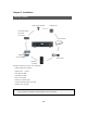
Chapter 12 — Appendix SPECIFICATION Screen Display 9CH 16CH Operating System Embedded Linux Compression H.264 Audio Algorithm G723.
ODD DVD-RW (optional) System Operation Front Keys, USB Mouse, IR Remote Control, Keyboard (Optional) Multi Language supported When inputting camera name, Korean’s available. Other Functions Pan/ Tilt are controlled to Mouse’s direction During backup, Viewer program is automatically saved and the files can be converted to AVI Power DC 12V 6A Operating Temperature 0℃ ~ 40℃ Dimension 428 mm(W) X 88mm(H) X 420mm(D) Weight 5.
Product Warranty This unit has thoroughly been tested and passed on quality control& quality assurance. Based on the warranty, If this unit malfunctions during normal use, you will be guaranteed to get your item repaired free of charge under joint agreement based on the warranty. [Tips on warranty]. ■ Check out the Warranty first. ■ Check the item again what is wrong with it and contact the seller of this unit.
■ For safe use of system and to prevent product failure or accident, please read this manual carefully before use. ■ The manual includes the product warranty. Be sure to keep it handy for later reference.