Owner’s Guide and Installation Manual 3BTR54XXXXD Series Fan CUL Model NO. : 3BTR54XXXXD Attach sales receipt to this card and retain as your proof of purchase DATE OF PURCHASE: RETAILER NAME: MODEL NUMBER: RETAILER ADDRESS: To register your fixture, please visit our website www.montecarlofans.com 9.9 kgs 21.
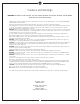
Cautions and Warnings WARNING: TO REDUCE THE RISK OF FIRE, ELECTRIC SHOCK, OR INJURY TO PERSONS, OBSERVE THE FOLLOWING READ AND SAVE THESE INSTRUCTIONS Installation work and electrical wiring must be done by qualified person(s) in accordance with applicable codes and standards (ANSI/NFPA 70), including fire-rated construction. Use this unit only in the manner intended by the manufacturer. If you have any questions contact the manufacturer.
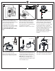
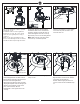
1 2 ON ON OFF OFF 3 Mounting bracket Before you begin installing the fan, Switch power off at Service panel and lock service disconnecting means to prevent power from being switched on accidentally. When the service disconnecting means cannot be locked, securely fasten a warning device, such as a tag, to the service panel. Use AC 120V/60HZ power supply only. 4 Before installing this fan make sure the outlet box is properly installed to the house structure.
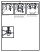
7 8 9 Tab Keeper pin Yoke cover Cross pin Slot Decorative plate Decorative setscrew Slip downrod into motor housing yoke, aligning holes and install cross pin and keeper pin. Insert cross pin through yoke and downrod until point appears on the other side, and insert keeper pin on cross pin. Pull the downrod up tight against the cross pin, and then evenly tighten the downrod set screws on motor housing yoke. Remove the decorative set screws. Keep the set screws.
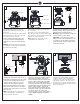
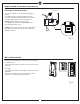
13 14 15 Stud Plate on motor Blade This side up Lift Canopy allowing the 2 studs to protrude through the canopy. Install knurled nuts as shown. Tighten the knurled nuts securely. The canopy should adjust for any irregularity in the ceiling or Outlet box. Make sure the studs protruding from the bottom of the Mounting bracket are installed with threads all the way through the bracket. Insert blade into the slot on flywheel.
19 20 21 Outer shade Decorative frame Remove 3 set screws from outer area of the light pan. keep screws. © 2018 Monte Carlo Fan Company Attached decorative frame onto the light pan. Align the holes on decorative frame with the screw holes on the light pan. Install it onto the light pan with 3 set screws removed in the installation step 19. 6 Attach the outer shade by locating dimples in the light pan with grooves on the glass and twist clockwise until tight.
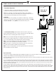
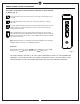
REMOTE CONTROL SETTING (Dimming/Non Dimming) Dimming Non Dimming Setting Rubber plug The remote controller is set with dimming function at factory. The “DIM” selection is the light dimmable selection. If you would make the light with on/off feature, remove the rubber plug from the receiver and switch it to ON/OFF position. Replace the rubber plug. The “ON/OFF” selection to make light ON/OFF only (non-dimming function) (Fig.
REMOTE CONTROL SETTING and OPERATION Transmitter Operation 1. Remove the battery seat from the bottom of remote control transmitter and install battery. Replace the battery seat. (Fig. 3) Back side of transmitter Note: Use a 3V battery. The battery will weaken with age and should be replaced before leaking as this will damage the transmitter. Dispose of used battery properly, keep the battery out of reach for children. Useful tips Remove battery seat by pushing at “A” position as shown in Fig.
REMOTE CONTROL SETTING and OPERATION The buttons on the remote control transmitter control the fan speed and light as follows. (Fig. 5) Press the button to get desired fan speed, Low to High and then High to Low cyclically. Press the OFF button to turn fan off. Fan speed will maintain last setting if turned off. Press this forward/reverse button to get desired airflow direction. Fan must be running to reverse. It will take about 25 seconds for fan to slow down and change rotation direction.
Trouble Shooting or wiring. In some cases, these installation errors may be mistaken for defects. If you experience any faults, installation, please call our Customer Service Center at the number printed on your parts list insert sheet. Warning means to prevent power from being switched on accidentally. When the service disconnecting means cannot be locked, securely fasten a prominent warning device, such as a tag, to the service panel. Trouble 1. If fan does not start: Suggested Remedy 1.
Sep.