Owner’s Guide and Installation Manual 3CLMR56XXXD-V1 Series Fan UL Model NO. : 3CLMR56XXXD-V1 Attach sales receipt to this card and retain as your proof of purchase DATE OF PURCHASE: RETAILER NAME: MODEL NUMBER: RETAILER ADDRESS: To register your fixture, please visit our website www.montecarlofans.com 9.3 kgs 20.
Cautions and Warnings WARNING: TO REDUCE THE RISK OF FIRE, ELECTRIC SHOCK, OR INJURY TO PERSONS, OBSERVE THE FOLLOWING READ AND SAVE THESE INSTRUCTIONS Installation work and electrical wiring must be done by qualified person(s) in accordance with applicable codes and standards (ANSI/NFPA 70), including fire-rated construction. Use this unit only in the manner intended by the manufacturer. If you have any questions contact the manufacturer.
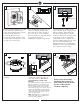
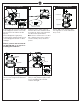
1 2 ON ON OFF OFF 3 Mounting plate Before you begin installing the fan, Switch power off at Service panel and lock service disconnecting means to prevent power from being switched on accidentally. When the service disconnecting means cannot be locked, securely fasten a warning device, such as a tag, to the service panel. 4 Before installing this fan make sure the outlet box is properly installed to the house structure.
7 8 9 Grounded wires Ungrounded wires After making the wire connections, the wires should be spread apart with the grounded conductor and the equipment-grounding conductor on one side of the outlet box and ungrounded conductor on the other side of the outlet box. The splices after being made should be turned upward and pushed carefully up into the outlet box.
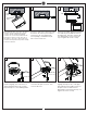
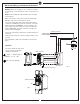
13 Install LED Light Kit 15 14 Install blanking plate LED Module Light shade Light plate LED light kit Reverse switch Connect white wire from fan to white wire from LED light kit and then connect blue wire from fan to black wire from LED light kit. Attach LED light kit to light pan by locating dimples in light pan with grooves on the LED light kit and twist clockwise until tight.
Wall Control Wiring, Installation and Operation Warning: Before proceeding, be sure to shut off electricity at main switch or circuit breaker in order to avoid electrical shock. Note: Before installing the wall transmitter, place it in OFF position. (Fig.2) Make series-wound connection for the wall controller with HOT wire from house and lead wires from fan.
Trouble Shooting ,I \RX KDYH GLI¿FXOW\ RSHUDWLQJ \RXU QHZ FHLOLQJ IDQ LW PD\ EH WKH UHVXOW RI LQFRUUHFW DVVHPEO\ LQVWDOODWLRQ RU ZLULQJ ,Q VRPH FDVHV WKHVH LQVWDOODWLRQ HUURUV PD\ EH PLVWDNHQ IRU GHIHFWV ,I \RX H[SHULHQFH DQ\ IDXOWV SOHDVH FKHFN WKLV 7URXEOH 6KRRWLQJ &KDUW ,I D SUREOHP FDQQRW EH UHPHGLHG RU \RX DUH H[SHULHQFLQJ GLI¿FXOW\ LQ LQVWDOODWLRQ SOHDVH FDOO RXU &XVWRPHU 6HUYLFH &HQWHU DW WKH QXPEHU SULQWHG RQ \RXU SDUWV OLVW LQVHUW VKHHW Warning %HIRUH VHUYLFLQJ RU FOHDQLQJ XQL
Mar.