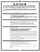
Owner’s Guide and Installation Manual 3CLNCSM60XXX Series Fan cETL Model NO. : 3CLNCSM60XX Attach sales receipt to this card and retain as your proof of purchase DATE OF PURCHASE: RETAILER NAME: MODEL NUMBER: RETAILER ADDRESS: To register your fixture, please visit our website www.montecarlofans.com 6.
Cautions and Warnings WARNING: TO REDUCE THE RISK OF FIRE, ELECTRIC SHOCK, OR INJURY TO PERSONS, FOLLOW THESE INSTRUCTIONS. Installation work and electrical wiring must be done by qualified person(s) in accordance with applicable codes and standards (ANSI/NFPA 70), including fire-rated construction. Use this unit only in the manner intended by the manufacturer. If you have any questions, contact the manufacturer.
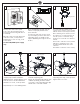
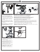
1 2 ON ON OFF OFF 3 Mounting bracket Switch power off at Service panel. Lock service disconnecting means to prevent power from being switched on accidentally. When the service disconnecting means cannot be locked, securely fasten a warning device, such as a tag, to the service panel. Before installing this fan make sure the outlet box is properly installed to the house structure.
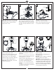
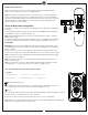
7 8 Decorative plate 9 Downrod Top cover Cross pin Keeper pin Rubber pad Yoke Snap a decorative plate onto each blade. Note: Make sure they are engaged with the blades firmly to make the blades aligned at the center. 10 Flip over the fan body with blades again. Place a rubber pad and a top cover over lead wires and safety cable and install the top cover onto the yoke with set screws provided. 11 Partially loosen downrod set screws from yoke at top of motor assembly.
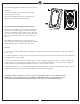
SAFETY CABLE INSTALLATION 13 14 Wall switch Power source Black Brown Grey Blue White Ground/Green Wi-Fi antenna Ground/Green Lag screw Canopy Receiver Black Safety cable White Washer Lock washer Safety cable must be installed into the house structure using 3” lag screws, washers, and lock washers provided, required for outdoor applications and in Canada (All fans installed in Canada), and for USA fan and light kit combinations over 35lbs.
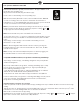
Remote Controller Operation Remove the battery cover from the remote control transmitter and install batteries. Replace the cover. This remote uses 2 1.5V/AAA batteries. Note: If not using for long periods of time, remove the batteries to prevent damage to remote controller, and store the remote controller away from excess heat or humidity. The batteries will weaken with age and should be replaced before they leak or corrode as this will damage the controller. Dispose of the used batteries properly.
Install Transmitter wall mount cradle with 2 screws provided. Useful tips: The remote transmitter can be removed by pressing it upward from the lower half. The remote transmitter can be held on magnetic metal materials by a magnet built in the transmitter. The receiver provides the following protective functions: Lock protection: The DC motor has a build-in safety feature against blade obstruction during operation.
Fan operation with Bond Home APP Download the Bond Home app with your smart devices. The app is available on the Google Play Store and Apple Store. Or get it from bond home link, http://bondhome.io/app Create a new account following on-screen operating steps. Make the fan (Smart by Bond wi-fi receiver) connection with wi-fi router.
Troubleshooting or wiring. In some cases, these installation errors may be mistaken for defects. If you experience any faults, installation, please call our Customer Service Center at the number printed on your parts list insert sheet. Warning and lock the service panel to prevent the power from being switched back on accidentally. If the service panel cannot be locked to prevent the power from being switched on accidentally, securely fasten a warning sign to the service panel. Trouble 1.
Aug.2021 Nov.