Owner’s Guide and Installation Manual 3DIR58XXD Series Fan UL Model NO. : 3DIR58XXD Attach sales receipt to this card and retain as your proof of purchase DATE OF PURCHASE: RETAILER NAME: MODEL NUMBER: RETAILER ADDRESS: To register your fixture, please visit our website www.montecarlofans.com 9.4 kgs 20.
Cautions and Warnings WARNING: TO REDUCE THE RISK OF FIRE, ELECTRIC SHOCK, OR INJURY TO PERSONS, OBSERVE THE FOLLOWING READ AND SAVE THESE INSTRUCTIONS Installation work and electrical wiring must be done by qualified person(s) in accordance with applicable codes and standards (ANSI/NFPA 70) including fire-rated construction. Use this unit only in the manner intended by the manufacturer. If you have any questions contact the manufacturer.
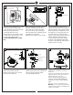
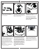
1 2 ON ON OFF OFF 3 Mounting bracket Before you begin installing the fan, Switch power off at Service panel and lock service disconnecting means to prevent power from being switched on accidentally. When the service disconnecting means cannot be locked, securely fasten a warning device, such as a tag, to the service panel. Use AC 120V/60HZ power supply only. 4 Downrod Mount Installation Before installing this fan make sure the outlet box is properly installed to the house structure.
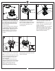
SAFETY CABLE INSTALLATION 8 9 Power source 7 Tab Black (Live) Wall switch White White (Neutral) Blue Black Ground/Green Lag screw Receiver Black Safety cable White Slot Washer Lock washer Install ball end of downrod into mounting bracket opening. Align (engage) slot on ball with tab on mounting bracket. Warning: Failure to align slot on ball with tab may result in serious injury.
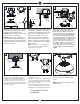
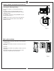
13 14 15 Hook Side cover Rubber pad Remove side covers from canopy exposing 4 holes. 2 closed holes and 2 open “L” shape holes. SAFETY CABLE INSTALLATION Reinstall the 3 set screws remove in step 12. Tighten screws securely. 17 18 Power source 16 Place rubber pad and canopy over lead wire and safety cable and align the larger holes in canopy and holes on rubber pad with the set screws on yoke.
20 19 21 Blade Plate on motor Light pan Install 2 of the screws to the side panel of mounting bracket corresponding to the open slotted holes on the canopy upper rim, screws provided. Remove the all thread studs from the lower part of the mounting bracket. Lift fan to mounting bracket, aligning the “L” shape holes with the screws on the mounting bracket. Turn the fan clockwise to lock in position. Install the other 2 canopy mounting set screws from the hardware pack and tighten all screws securely.
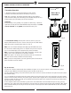
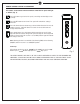
REMOTE CONTROL SETTING (Dimming/Non Dimming) Dimming Non Dimming Setting The remote controller is set with dimming function at factory. The “DIM” selection is the light dimmable selection. If you would make the light with on/off feature, switch it to ON/OFF position. The “ON/OFF” selection to make light ON/OFF only (non dimming function) (Fig. 1 ) DIM ON/OFF Caution: If the remote receiver has been wired with fan, turn power off by wall switch before switch “DIM” and “ON/OFF” selection. Fig.
REMOTE CONTROL SETTING and OPERATION Transmitter Operation 1. Remove the battery seat from the bottom of remote control transmitter and install battery. Replace the battery seat. (Fig. 3) Back side of transmitter Note: Use a 3V battery. The battery will weaken with age and should be replaced before leaking as this will damage the transmitter. Dispose of used battery properly, keep the battery out of reach for children. Useful tips Remove battery seat by pushing at “A” position as shown in Fig.
REMOTE CONTROL SETTING and OPERATION The buttons on the remote control transmitter control the fan speed and light as follows. (Fig. 5) Press the button to get desired fan speed, Low to High and then High to Low cyclically. Press the OFF button to turn fan off. Fan speed will maintain last setting if turned off. Press this forward/reverse button to get desired airflow direction. Fan must be running to reverse. It will take about 25 seconds for fan to slow down and change rotation direction.
Trouble Shooting or wiring. In some cases, these installation errors may be mistaken for defects. If you experience any faults, installation, please call our Customer Service Center at the number printed on your parts list insert sheet. Warning: Before servicing or cleaning unit, Switch power off at Service panel and lock service disconnecting means to prevent power from being switched on accidentally.
Nov.