Owner’s Guide and Installation Manual 3JVR52XXX Series Fan CUL Model NO. : 3JVR52XX Attach sales receipt to this card and retain as your proof of purchase DATE OF PURCHASE: RETAILER NAME: MODEL NUMBER: RETAILER ADDRESS: To register your fixture, please visit our website www.montecarlofans.com 6.28 kg 13.
Cautions and Warnings WARNING: TO REDUCE THE RISK OF FIRE, ELECTRIC SHOCK, OR INJURY TO PERSONS, OBSERVE THE FOLLOWING READ AND SAVE THESE INSTRUCTIONS Installation work and electrical wiring must be done by qualified person(s) in accordance with applicable codes and standards (ANSI/NFPA 70), including fire-rated construction. Use this unit only in the manner intended by the manufacturer. If you have any questions contact the manufacturer.
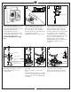
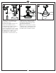
1 2 ON 3 ON Mounting bracket OFF OFF Before you begin installing the fan, Switch power off at Service panel and lock service disconnecting means to prevent power from being switched on accidentally. When the service disconnecting means cannot be locked, securely fasten a warning device, such as a tag, to the service panel. Use AC 120V/60HZ power supply only. Before installing this fan make sure the outlet box is properly installed to the house structure.
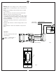
7 8 9 Canopy Tab Canopy bottom cap Slot Keeper pin Yoke cover Cross pin Downrod Place downrod over canopy, canopy bottom cap and yoke cover. Thread lead wires and safety cable from motor assembly through downrod. Slip downrod into motor housing yoke, aligning holes and install cross pin and keeper pin. Insert cross pin through yoke and downrod until point appears on the other side, and insert keeper pin on cross pin.
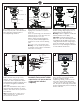
13 14 15 Reverse switch Canopy bottom cap Partially loosen one and remove one preassembled screw from mounting bracket. Save screw. Lift canopy up, aligning its keyhole slot with the preassembled screw on mounting bracket and twist clockwise to lock in place. Reinstall the screw removed and tighten all screws securely. Attach canopy bottom cap onto canopy by aligning its holes with the screws on mounting bracket and fix it with the magnet which is embedded in the cap.
Warning: Before proceeding, be sure to shut off electricity at main switch or circuit breaker in order to avoid electrical shock. Note: Before installing the wall transmitter, place it in OFF position. (Fig.2) Make series-wound connection for the wall controller with HOT wire from house and lead wires from fan.
Troubleshooting or wiring. In some cases, these installation errors may be mistaken for defects. If you experience any faults, installation, please call our Customer Service Center at the number printed on your parts list insert sheet. Warning and lock the service panel to prevent the power from being switched back on accidentally. If the service panel cannot be locked to prevent the power from being switched on accidentally, securely fasten a warning sign to the service panel. Trouble 1.
Dec.