Owner’s Guide and Installation Manual 3MNLR56XXD Series Fan ETL Model NO. : 3MNLR56 Attach sales receipt to this card and retain as your proof of purchase DATE OF PURCHASE: RETAILER NAME: MODEL NUMBER: RETAILER ADDRESS: To register your fixture, please visit our website www.montecarlofans.com 7.74 kgs 17.
Cautions and Warnings WARNING: TO REDUCE THE RISK OF FIRE, ELECTRIC SHOCK, OR INJURY TO PERSONS, OBSERVE THE FOLLOWING READ AND SAVE THESE INSTRUCTIONS Installation work and electrical wiring must be done by qualified person(s) in accordance with applicable codes and standards (ANSI/NFPA 70-1999), including fire-rated construction. Use this unit only in the manner intended by the manufacturer. If you have any questions contact the manufacturer.
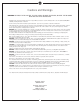
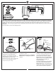
1 2 3 Ceiling joist Ceiling Outlet Box ON ON Ceiling Joists OFF Mounting Bracket Screw/ Washers /Spring Washers OFF 2˝ x 4˝ Outlet Box Before you begin installing the fan, Switch power off at Service panel and lock service disconnecting means to prevent power from being switched on accidentally. When the service disconnecting means cannot be locked, securely fasten a warning device, such as a tag, to the service panel.
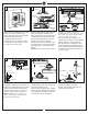
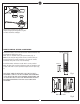
7 Fan wires Safety cable 8 Light wires 9 Column Downrod/Hanger Ball Assembly Downrod Keeper pin Fan Wiring Philips screwdriver Yoke Canopy Column Cover Cross pin Yoke Cross pin Canopy ring Set screw Column Column cover Connect the lead wires and thread safety cable from motor assembly through downrod.
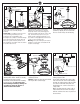
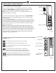
13 Green From Hanger Ball Green From Mounting Bracket White- AC IN N 2P plug 3P plug Receiver Wall Switch Black- AC IN L Green or Bare Ground Green or Bare Ground Receiver 120V Supply (Power Supply) Make wiring connections using plugs with lead wires and wire connectors provided as indicated above. Connect the 2 P plug from fan to 2 P plug from receiver and then connect the 3 P plug from fan to the 3 P plug from receiver.
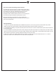
17 Attach glass to light pan by locating dimples in light pan with grooves in glass and twist clockwise until tight. REMOTE CONTROL SETTING and OPERATION Remove the battery cover from the remote control transmitter and install battery. Replace the cover. Note: Use 2 1.5V/AAA battery to replace battery. (Fig. 1) Note: If not using for long periods of time, remove battery to prevent damage to remote transmitter, and store the remote transmitter away from excess heat or humidity.
REMOTE CONTROL SETTING and OPERATION Universal Mode and Learning Mode Dip(Code) Switches There are “Universal Mode” and “Learning Mode” with the remote controller. Upper position If choosing “Universal Mode”, simply place both dip (code) switch at UPPER position. Your fan with the remote controller is ready to use. (Fig. 3) Lower position Note: If using universal mode, your fan can be controlled with other remote transmitters with the same setting.
The receiver provides the following protective functions Lock protection- The DC motor has a build-in safety feature against blade or motor obstruction during operation. If something obstructs the fan blades or motor, the motor will keep trying to run for 3 times and then stop operation after about 30 seconds of interruption. Please remove obstacles and reset. To reset it by turn the fan off by remote transmitter and then turn the fan on.
Trouble Shooting or wiring. In some cases, these installation errors may be mistaken for defects. If you experience any faults, installation, please call our Customer Service Center at the number printed on your parts list insert sheet. Warning: Before servicing or cleaning unit, Switch power off at Service panel and lock service disconnecting means to prevent power from being switched on accidentally.
Nov.