Owner’s Guide and Installation Manual 4BFR54XXD Series Fan UL Model NO. : 4BFR54(X) (For damp location fan) Attach sales receipt to this card and retain as your proof of purchase DATE OF PURCHASE: RETAILER NAME: MODEL NUMBER: RETAILER ADDRESS: To register your fixture, please visit our website www.montecarlofans.com 9.7 kgs 21.
Cautions and Warnings WARNING: TO REDUCE THE RISK OF FIRE, ELECTRIC SHOCK, OR INJURY TO PERSONS, OBSERVE THE FOLLOWING READ AND SAVE THESE INSTRUCTIONS Installation work and electrical wiring must be done by qualified person(s) in accordance with applicable codes and standards (ANSI/NFPA 70-1999), including fire-rated construction. Use this unit only in the manner intended by the manufacturer. If you have any questions contact the manufacturer.
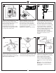
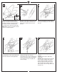
1 2 ON 3 ON Mounting bracket OFF OFF Before you begin installing the fan, Switch power off at Service panel and lock service disconnecting means to prevent power from being switched on accidentally. When the service disconnecting means cannot be locked, securely fasten a warning device, such as a tag, to the service panel. 4 Before installing this fan make sure the outlet box is properly installed to the house structure.
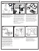
7 SAFETY CABLE INSTALLATION 8 9 Tab Slot Lag screw ON Safety cable Dip switches Washer Lock washer Install ball end of downrod into mounting bracket opening. Align (engage) slot on ball with tab on mounting bracket. Warning: Failure to align slot on ball with tab may result in serious injury. For Canadian installation and for USA fan and light kit combinations over 35 lbs, in both flush and downrod modes the safety cable must be installed into the house structure beams using 1.
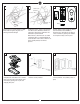
13 14 15 Long blade Light pan Screw holes Short blade Upper coupler Lower coupler Insert the short blade into the lower couplers and then insert the long blade into upper couplers on the hubs. Repeat this process for the remaining blades assemblies on the other side of the hubs. Note: Make sure the screw holes in blade frames are installed upward. 16 Align the screws holes in blade frame and the holes in the coupler and then fix the blades in the couplers with set screws provided.
19 21 20 Left hand side (Forward) Reverse switch Battery cover Right hand side (Reverse) Glass Attach glass by locating dimples in light fixture with the groves in glass and twisting clockwise till tight. 22 HAND HELD INSTALL Place battery cover over battery compartment and buttons. Place remote over 2 pins on front cover. Attach cover of remote by placing over 4 pins and snapping into place.
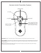
Remote Control Transmitter Features MEDIUM SPEED LED LIGHT HIGH SPEED LOW SPEED LIGHT ON/OFF SETTING AND DIMMER (Press and hold to dim light infinitely) FAN OFF SETTING (Turn fan off only) FAN SPEED: Depress “1 dot” for low speed, “2 dots” for medium or “3 dots” for high. To turn fan off press square”. LIGHT DIMMER: To turn light on, press light dimmer once quickly. To turn off press once quickly while light is on. To dim light hold down button “light dimmer”.
Trouble Shooting or wiring. In some cases, these installation errors may be mistaken for defects. If you experience any faults, installation, please call our Customer Service Center at the number printed on your parts list insert sheet. Warning: Before servicing or cleaning unit, Switch power off at Service panel and lock service disconnecting means to prevent power from being switched on accidentally.
Jan.2014 Apr.12.