Owner’s Guide and Installation Manual 3MO52XXO-L / 3MTR38XXO-L Series Fans UL Model Number of 3MO52XXO-L: 52HH UL Model Number of 3MTR38XXO-L: 38HH Attach sales receipt to this card and retain as your proof of purchase DATE OF PURCHASE: RETAILER NAME: MODEL NUMBER: RETAILER ADDRESS: To register your fixture, please visit our website www.montecarlofans.
WARNING: TO REDUCE THE RISK OF FIRE, ELECTRIC SHOCK, OR INJURY TO PERSONS, OBSERVE THE FOLLOWING READ AND SAVE THESE INSTRUCTIONS Installation work and electrical wiring must be done by qualified person(s) in accordance with applicable codes and standards (ANSI/NFPA 70-1999), including fire-rated construction. Use this unit only in the manner intended by the manufacturer. If you have any questions contact the manufacturer.
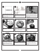
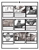
1 Before you begin installing the fan, Switch power off at Service panel and lock service disconnecting means to prevent power from being switched on accidentally. When the service disconnecting means cannot be locked, securely fasten a prominent warning device, such as a tag, to the service panel. 4 Place the fan body with the light fitter pointing upward. Attache the 3 blades as shown above. 7 Place the blade ring holder over the leadwires and safety cable.
10 12 11 Reverse switch Cross pin Reverse switch Set screw Re-place the upper motor housing onto the fan motor. Be sure the holes are all aligned. Note: Align the hole on top housing labeled “REVERSE” with the reverse switch. Tighten the screws removed from step 5. Tighten securely. Loosen set screw and then remove cross pin from yoke for downrod to slip into yoke. Keep the cross pin for later use. 13 14 15 Thread the leadwires and safety cable through the downrod.
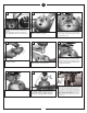
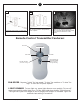
20 19 21 white Red Remote Transmitter Dip swtiches Make wiring connections as indicated above. White from fan to white from remote marked N. Blue from fan to blue from remote marked light. Black from fan to Red from remote marked L. White from house to white from remote marked AC N . Black from house to Black from remote marked AC L. Connect all green ground wires to Ground wire from House. 22 Make wire connections to power source using wire nuts provided.
28 WALL MOUNT INSTALL 30 29 Reverse switch Attach front cover to wall control with screws provided. Snap battery cover in place. Install wall control unit to outlet box using machine screws provided. Reverse function for this fan is a switch on top housing of the fan body. Turn fan off and flip switch this will reverse the direction of the blades.
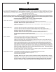
TROUBLE SHOOTING If you have difficulty operating your new ceiling fan, it may be the result of incorrect assembly, installation, or wiring. In some cases, these installation errors may be mistaken for defects. If you experience any faults, please check this Trouble Shooting Chart. If a problem cannot be remedied, or you are experiencing difficulty in installation, please call our Customer Service Center at the number printed on your parts list insert sheet.
Dec.2011 new format Jan.2011 Update customer service phone number May.