Owner’s Guide and Installation Manual 3TF24XX Series Fan UL Model No. : AC-536 Attach sales receipt to this card and retain as your proof of purchase DATE OF PURCHASE: RETAILER NAME: MODEL NUMBER: RETAILER ADDRESS: To register your fixture, please visit our website www.montecarlofans.com 4.88 kgs 10.
WARNING: TO REDUCE THE RISK OF FIRE, ELECTRIC SHOCK, OR INJURY TO PERSONS, OBSERVE THE FOLLOWING READ AND SAVE THESE INSTRUCTIONS Installation work and electrical wiring must be done by qualified person(s) in accordance with applicable codes and standards (ANSI/NFPA 70-1999), including fire-rated construction. Use this unit only in the manner intended by the manufacturer. If you have any questions contact the manufacturer.
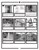
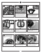
1 3 2 Use metal outlet box suitable for fan support (must support 35 lbs). Before attaching fan to outlet box, ensure the outlet box is securley fastened by at least two points to a structural ceiling member ( a loose box will cause the fan to wabble). Use only the screws provided with the outlet box. Before you begin installing the fan, Switch power off at Service panel and lock service disconnecting means to prevent power from being switched on accidentally.
10 Safety cable installation 11 12 Make sure the studs protruding from the bottom of the Mounting bracket are installed with threads all the way through the bracket. Hang assembled fan from the mounting bracket installed to ceiling in previous step. Make sure the fan is hanging straight. Rotate fan until the tab on the Mounting bracket engages the slot on the Downrod Ball. This must be done to prevent the fan body from rotating when the blades are in motion.
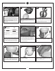
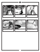
20 19 Canopy Center Hole 21 Larger holes Smaller holes Remove 2 screws in yoke (see insert). Remove 3 screws with keyhole slots from top of fan. 22 Hands free hook Place canopy on top of the fan motor allowing the yoke, wires and safety cable to pass through the large hole in the center of the canopy. Align the 3 larger holes around the center hole with the 3 screws still installed in the fan.
28 29 30 Connect plug from fan to switch house plug. Black capacitor box needs to be stuck to the switch housing. Not being attached can cause motor noise. Remove twin adhesive tape from the black capacitor as shown above. 31 32 33 Place and press firmly on the capacitor to stick it to the switch housing. Be sure it is secure. Remove 3 screws and save to install switch housing. Install the switch housing using the 3 screws previously removed.
TROUBLe SHOOTING If you have difficulty operating your new ceiling fan, it may be the result of incorrect assembly, installation, or wiring. In some cases, these installation errors may be mistaken for defects. If you experience any faults, please check this Trouble Shooting Chart. If a problem cannot be remedied, or you are experiencing difficulty in installation, please call our Customer Service Center at the number printed on your parts list insert sheet.
Mar.2012 New format Jul.