Owner’s Guide and Installation Manual CHICAGO,IL MOTOR SIZE: DC155x22 WATTS: 40W 4GIR60XXX Series Fan cETL Model NO. : 4GIR60XXX Attach sales receipt to this card and retain as your proof of purchase DATE OF PURCHASE: RETAILER NAME: MODEL NUMBER: RETAILER ADDRESS: To register your fixture, please visit our website www.montecarlofans.com 8.9 kg 19.
Cautions and Warnings WARNING: TO REDUCE THE RISK OF FIRE, ELECTRIC SHOCK, OR INJURY TO PERSONS, OBSERVE THE FOLLOWING READ AND SAVE THESE INSTRUCTIONS Installation work and electrical wiring must be done by qualified person(s) in accordance with applicable codes and standards (ANSI/NFPA 70), including fire-rated construction. Use this unit only in the manner intended by the manufacturer. If you have any questions contact the manufacturer.
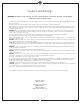
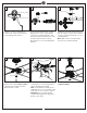
1 2 ON 3 ON Mounting bracket OFF OFF Before you begin installing the fan, Switch power off at Service panel and lock service disconnecting means to prevent power from being switched on accidentally. When the service disconnecting means cannot be locked, securely fasten a warning device, such as a tag, to the service panel. Use AC 120V/60HZ power supply only. 4 Before installing this fan make sure the outlet box is properly installed to the house structure.
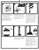
7 8 SAFETY CABLE INSTALLATION 9 Pin Canopy CHICAGO,IL MOTOR SIZE: DC155x22 WATTS: 40W Tab CHICAGO,IL MOTOR SIZE: DC155x22 WATTS: 40W Canopy bottom cap Decorative kit Lag screw Safety cable Slot Washer Lock washer Place decorative kit canopy bottom cap and canopy over lead wires, safety cable and downrod, and then replace the hanger ball. Replace the hanger ball with pin and set screw and tighten securely. Warning: Make sure the pin is installed well on hanger ball with downrod.
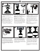
13 14 15 This side up Blade bracket coupler Blade Countersunk set screw Blade bracket Partially loosen the countersunk set screws on the coupler of blade bracket. Use the Allen wrench provided. 16 Insert a blade bracket into the coupler. Align the holes on the coupler with the screw holes on the blade bracket, and then fix the blade bracket with set screws provided. Tighten screws securely. Repeat this process for remaining blade brackets.
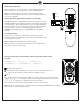
Remote Controller Operation Remove the battery cover from the remote control transmitter and install batteries. Replace the cover. This remote uses 2 1.5V/AAA batteries.
Install Transmitter wall mount cradle with 2 screws provided. The receiver provides the following protective functions Lock protection- The DC motor has a build-in safety feature against blade obstruction during operation. If something obstructs the fan blades, the motor will stop operation after about 20 seconds of interruption. Please remove obstacles and reset it by turning the power off, and turn it back.
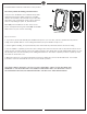
Trouble Shooting or wiring. In some cases, these installation errors may be mistaken for defects. If you experience any faults, installation, please call our Customer Service Center at the number printed on your parts list insert sheet. Warning means to prevent power from being switched on accidentally. When the service disconnecting means cannot be locked, securely fasten a prominent warning device, such as a tag, to the service panel. Trouble 1. If fan does not start: Suggested Remedy 1.
Jan.