Owner’s Guide and Installation Manual 4LMR56XXXD Series Fan cETL Model NO. : 4LMR56XXXD Attach sales receipt to this card and retain as your proof of purchase DATE OF PURCHASE: RETAILER NAME: MODEL NUMBER: RETAILER ADDRESS: To register your fixture, please visit our website www.montecarlofans.com 7.4 kg 16.
Cautions and Warnings WARNING: TO REDUCE THE RISK OF FIRE, ELECTRIC SHOCK, OR INJURY TO PERSONS, OBSERVE THE FOLLOWING READ AND SAVE THESE INSTRUCTIONS Installation work and electrical wiring must be done by qualified person(s) in accordance with applicable codes and standards (ANSI/NFPA 70), including fire-rated construction. Use this unit only in the manner intended by the manufacturer. If you have any questions contact the manufacturer.
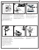
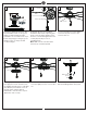
1 2 3 Mounting bracket ON ON Canopy OFF OFF Canopy ring Before you begin installing the fan, Switch power off at Service panel and lock service disconnecting means to prevent power from being switched on accidentally. When the service disconnecting means cannot be locked, securely fasten a warning device, such as a tag, to the service panel. Use AC 120V/60HZ power supply only. 4 Before installing this fan make sure the outlet box is properly installed to the house structure.
7 8 SAFETY CABLE INSTALLATION 9 Tab Cross pin Lag screw Keeper pin Safety cable Slot Washer Lock washer Install ball end of downrod into mounting bracket opening. Align (engage) slot on ball with tab on mounting bracket. Warning: Failure to align slot on ball with tab may result in serious injury. Important: If using the angle mount, make sure open end of mounting bracket is installed facing the higher point of the ceiling and make sure the ceiling angle is not steeper than 20º.
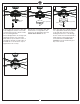
12 This side up This side up Este lado haciaarriba Haut 11 13 Blade Blade supporting plate Groove Lift Canopy, aligning the key holes with the preinstalled screws on canopy and turning clockwise till tight, and then reinstall the set screw removed in step 3. Install canopy ring by locating its groove with the screws on canopy and turn clockwise till tight. 14 Plate on motor Insert blade into the slot on flywheel.
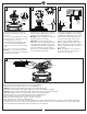
17 18 19 LED light fixture Inner light shade Nut Connect white wire from fan to white wire from LED light kit and then connect blue (or black) wire from fan to black (or blue) wire from LED light fixture. Attach LED light fixture onto the light pan, aligning the keyhole slots on the light fixture with the preassembled screws on the light pan and twist clockwise till lock. Reinstall the screw removed in step 15. Tighten all screws securely.
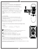
Remote Controller Operation Remove the battery cover from the remote control transmitter and install batteries. Replace the cover. This remote uses 2 1.5V/AAA batteries.
Install Transmitter wall mount cradle with 2 screws provided. Useful tips: Take remote transmitter up by pushing it at lower area of the transmitter. The remote transmitter can be held on magnetic metal materials by a magnet built in the transmitter. Wall mount cradle The receiver provides the following protective functions Lock protection- The DC motor has a build-in safety feature against blade obstruction during operation.
Trouble Shooting or wiring. In some cases, these installation errors may be mistaken for defects. If you experience any faults, installation, please call our Customer Service Center at the number printed on your parts list insert sheet. Warning means to prevent power from being switched on accidentally. When the service disconnecting means cannot be locked, securely fasten a prominent warning device, such as a tag, to the service panel. Trouble 1. If fan does not start: Suggested Remedy 1.
Mar.