Owner’s Guide and Installation Manual 5DISM52XXXD Series Fan cETL Model NO. : 5DISM52XXD Attach sales receipt to this card and retain as your proof of purchase DATE OF PURCHASE: RETAILER NAME: MODEL NUMBER: RETAILER ADDRESS: To register your fixture, please visit our website www.montecarlofans.com 7.3 kg 16.
Cautions and Warnings WARNING: TO REDUCE THE RISK OF FIRE, ELECTRIC SHOCK, OR INJURY TO PERSONS, OBSERVE THE FOLLOWING READ AND SAVE THESE INSTRUCTIONS Installation work and electrical wiring must be done by qualified person(s) in accordance with applicable codes and standards (ANSI/NFPA 70) including fire-rated construction. Use this unit only in the manner intended by the manufacturer. If you have any questions contact the manufacturer.
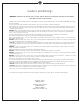
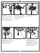
1 2 ON ON OFF OFF 3 Mounting bracket Before you begin installing the fan, Switch power off at Service panel and lock service disconnecting means to prevent power from being switched on accidentally. When the service disconnecting means cannot be locked, securely fasten a warning device, such as a tag, to the service panel. Use AC 120V/60HZ power supply only. 4 Before installing this fan make sure the outlet box is properly installed to the house structure.
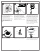
7 8 SAFETY CABLE INSTALLATION 9 Tab Cross pin Lag screw Keeper pin Safety cable Slot Washer Lock washer Slip downrod into motor housing yoke, aligning holes and install cross pin and keeper pin. Insert cross pin through yoke and downrod until point appears on the other side, and insert keeper pin on cross pin. Pull the downrod up tight against the cross pin, and then evenly tighten the downrod set screws on motor housing yoke. Place yoke cover on top housing of fan.
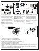
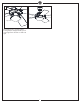
11 12 13 Blade Stud Plate on motor Lift Canopy allowing the 2 studs to protrude through the canopy. Install knurled nuts as shown. Tighten the knurled nuts securely. The canopy should adjust for any irregularity in the ceiling or Outlet box. Make sure the studs protruding from the bottom of the Mounting bracket are installed with threads all the way through the bracket. Insert blade into the slot on flywheel.
17 Light shade Attach light shade to the light pan by locating dimples in light pan with grooves on the light shade and twist clockwise till tight.
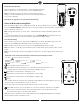
Remote Controller Operation Remove the battery cover from the remote control transmitter and install batteries. Replace the cover. This remote uses 2 1.5V/AAA batteries. Note: If not using for long periods of time, remove battery to prevent damage to remote transmitter, and store the remote transmitter away from excess heat or humidity. LEARN 0 1 LEARN Note: Refer to page 9 for fan operation with Bond app.
Screw cover Install Transmitter wall mount cradle with 2 screws provided. Ensure the arrow on wall mount cradle is pointing upward. Cover the set screws with screw covers. Wall mount cradle Arrow The receiver provides the following protective functions Lock protection- The DC motor has a build-in safety feature against blade obstruction during operation. If something obstructs the fan blades, the motor will stop operation after about 20 seconds of interruption.
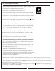
Fan operation with Bond Home APP Download the Bond Home app with your smart devices. The app is available on the Google Play Store and Apple Store. Or get it from bond home link, http://bondhome.io/app Create a new account following on-screen operating steps. Make the fan (Smart by Bond wi-fi receiver) connection with wi-fi router.
Trouble Shooting or wiring. In some cases, these installation errors may be mistaken for defects. If you experience any faults, installation, please call our Customer Service Center at the number printed on your parts list insert sheet. Warning means to prevent power from being switched on accidentally. When the service disconnecting means cannot be locked, securely fasten a prominent warning device, such as a tag, to the service panel. Trouble 1. If fan does not start: Suggested Remedy 1.
© 2021 Monte Carlo Fan Collections 11 1/2021