Owner’s Guide and Installation Manual 5DI52XXD/5DI52XXD-L Series Fan UL Model No. : 5DI52 Attach sales receipt to this card and retain as your proof of purchase DATE OF PURCHASE: RETAILER NAME: MODEL NUMBER: RETAILER ADDRESS: To register your fixture, please visit our website www.montecarlofans.com 8.5 kgs 18.
WARNING: TO REDUCE THE RISK OF FIRE, ELECTRIC SHOCK, OR INJURY TO PERSONS, OBSERVE THE FOLLOWING: READ AND SAVE THESE INSTRUCTIONS Installation work and electrical wiring must be done by qualified person(s) in accordance with applicable codes and standards (ANSI/NFPA 70-1999), including fire-rated construction. Use this unit only in the manner intended by the manufacturer. If you have any questions contact the manufacturer.
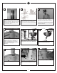
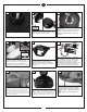
1 2 3 Before you begin installing the fan, Switch power off at Service panel and lock service disconnecting means to prevent power from being switched on accidentally. When the service disconnecting means cannot be locked, securely fasten a prominent warning device, such as a tag, to the service panel. Before installing this fan make sure the outlet box is properly installed to the house structure.
10 11 12 Safety cable installation Safety Cable Lag Screw safety cable washer 3” lag screw Tighten the 2 set screws on the yoke once the downrod is in place. 13 Make sure the studs protruding from the bottom of the Mounting bracket are installed with threads all the way through the bracket. Hang assembled fan from the mounting bracket installed to ceiling in previous step. Make sure the fan is hanging straight. Rotate fan until the tab on the Mounting bracket engages the slot on the Downrod Ball.
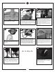
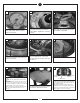
20 19 18 “L” shape slots Install rubber pad between fan body and canopy. Remove side covers from canopy exposing 4 holes. 2 closed holes and 2 open “L” shape holes and then Pass leadwires and safety cable through the canopy. Place canopy over fan body aligning holes. Replace the 3 screws removed and tighten securely. Check motor for shipping stabilizers and remove if present.
27 28 29 Loosen 2 screws and remove 1 screw from motor plate. Save removed screw for use later. Install by twisting clockwise, add 1 screw removed step 27 to switch housing plate. Tighten the 3 screws securely. Connect plug from fan to switch house plug. Be sure plugs connection snap together completely. 30 31 32 Loosen the pre installed screws of switch housing plate. Save removed screw for use later. Connect white wire from fan to white wire from light fixture.
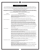
TROUBLE SHOOTING If you have difficulty operating your new ceiling fan, it may be the result of incorrect assembly, installation, or wiring. In some cases, these installation errors may be mistaken for defects. If you experience any faults, please check this Trouble Shooting Chart. If a problem cannot be remedied, or you are experiencing difficulty in installation, please call our Customer Service Center at the number printed on your parts list insert sheet.
Apr.2013 May.2013 CUL requirement Aug.2013 dual mount Jul.