Owner’s Guide and Installation Manual 5HS52XXD-L/5HS52XXS-L Series Fan UL Model No. : 52-ANT Attach sales receipt to this card and retain as your proof of purchase DATE OF PURCHASE: RETAILER NAME: MODEL NUMBER: RETAILER ADDRESS: To register your fixture, please visit our website www.montecarlofans.com 7.7kgs 17.
WARNING: TO REDUCE THE RISK OF FIRE, ELECTRIC SHOCK, OR INJURY TO PERSONS, OBSERVE THE FOLLOWING READ AND SAVE THESE INSTRUCTIONS Installation work and electrical wiring must be done by qualified person(s) in accordance with applicable codes and standards (ANSI/NFPA 70-1999), including fire-rated construction. Use this unit only in the manner intended by the manufacturer. If you have any questions contact the manufacturer.
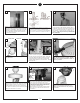
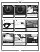
2 3 Before you begin installing the fan, Switch power off at Service panel and lock service disconnecting means to prevent power from being switched on accidentally. When the service disconnecting means cannot be locked, securely fasten a prominent warning device, such as a tag, to the service panel. Before installing this fan make sure the outlet box is properly installed to the house structure.
10 12 11 House Black Fan Blue Black White White Ground Green Connect black and blue wire from fan to Black or (Hot) wire from house. Connect White wire from Fan to White (Neutral) wire from house. Connect Ground leads from mounting bracket and downrod to Ground lead from house. Refer to Safety Tips section of manual. 13 Cover Ring Make wire connections to power source using wire nuts provided. Make sure that no filiments are outside of the wirenut.
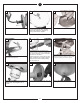
19 21 20 Hands free hook Place canopy over fan body aligning holes. Replace the 3 screws removed and tighten securely. Check motor for shipping stabilizers and remove if present. Remove the all thread studs from the lower part of the mounting bracket. Hang fan from mounting bracket by the hands free hook into a closed hole on the edge of the Canopy. Note: For Canadian mounting refer to Step #8.
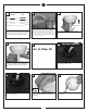
28 29 30 Remove nut and save for next step. Remove switch cap housing from fan. Remove the plug of fitter. Install switch cap housing to light kit by turning clockwise to tighten. Install keeper nut over lead wires. 31 32 33 Tighten keeper nut onto threaded pipe from the light kit. Install 3 x 60 watt Candelabra base bulbs. WARNING: Over lamping the fan will result in the fan lights shutting down until the proper wattage of bulbs are installed.
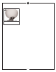
37 Install finial cap and finial nut to glass and tighten finial nut.
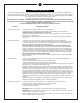
TROUBLe SHOOTING If you have difficulty operating your new ceiling fan, it may be the result of incorrect assembly, installation, or wiring. In some cases, these installation errors may be mistaken for defects. If you experience any faults, please check this Trouble Shooting Chart. If a problem cannot be remedied, or you are experiencing difficulty in installation, please call our Customer Service Center at the number printed on your parts list insert sheet.
Dec.2011 New formate Jan.2012 Update customer service phone number Jun.