Owner’s Guide and Installation Manual 5LCM52XX Series Fan UL Model NO. : AC-552AL Attach sales receipt to this card and retain as your proof of purchase DATE OF PURCHASE: RETAILER NAME: MODEL NUMBER: RETAILER ADDRESS: To register your fixture, please visit our website www.montecarlofans.com 9.4 kgs 20.
Cautions and Warnings WARNING: TO REDUCE THE RISK OF FIRE, ELECTRIC SHOCK, OR INJURY TO PERSONS, OBSERVE THE FOLLOWING READ AND SAVE THESE INSTRUCTIONS Installation work and electrical wiring must be done by qualified person(s) in accordance with applicable codes and standards (ANSI/NFPA 70-1999), including fire-rated construction. Use this unit only in the manner intended by the manufacturer. If you have any questions contact the manufacturer.
Preparation Warning: Before starting assembly of this product, please disconnect power to area and familiarize yourself with the safety information provided on page 2. A Determine mounting method to use. C A - Downrod Mount B - Angle Mount Important: If using the angle mount, check to make sure the ceiling angle is not steeper B than 18º. Important: If using the angle mount, make sure open end of mounting bracket is installed facing the higher point of the ceiling.
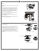
Installation Instruction (Downrod Mount) Downrod Partially loosen downrod set screws from yoke at top of motor assembly. Remove keeper pin and cross pin from yoke, and save for later use. Place downrod over canopy and yoke cover. Thread lead wires and safety cable from motor assembly through downrod. Slip downrod into motor housing yoke, aligning holes and install cross pin and keeper pin. Insert cross pin through yoke and downrod until point appears on the other side, and insert keeper pin on cross pin.
Installation Instruction (Flushmount) Fig. 5 Remove canopy cover by turning counterclockwise. There are 6 holes on the bottom of the canopy, 3 of them are larger. (Fig. 5) Canopy cover Screws Thread lead wires and safety cable through canopy. Place canopy over yoke, aligning larger holes in canopy with the 3 existing screws on top of motor housing. Install 3 screws with lock washers (these screws with lock washers will be located in the hardware pack) into the remaining holes.
Wall Switch White Wiring Black Warning: Make sure main power is turned off before making wiring. Power Line Grounded/ Green Black Make wire connections as indicated. Connect Black, Blue and Orange wire from fan to Black (Hot) wire from house. Connect White wire from Fan to White (Neutral) wire from house. Connect all green grounded wires from fan to Grounded wire from House. Make sure that no filaments are outside of the wire connectors. (Fig. 7) Orange Blue White Fig.
Blade installation Install blade bracket with blade by 3 blade screws and washers provided. Tighten screws securely. Repeat this process for remaining blades. (Fig. 9) Remove shipping stabilizers from motor assembly. Install the blade assembly to motor using the preinstalled screws. Tighten screws securely. Repeat this process for remaining blade assemblies. (Fig. 9) 電容器 電容器 Screws Note: Tighten blade bracket screws twice a year.
Trouble Shooting ,I \RX KDYH GLI¿FXOW\ RSHUDWLQJ \RXU QHZ FHLOLQJ IDQ LW PD\ EH WKH UHVXOW RI LQFRUUHFW DVVHPEO\ LQVWDOODWLRQ RU ZLULQJ ,Q VRPH FDVHV WKHVH LQVWDOODWLRQ HUURUV PD\ EH PLVWDNHQ IRU GHIHFWV ,I \RX H[SHULHQFH DQ\ IDXOWV SOHDVH FKHFN WKLV 7URXEOH 6KRRWLQJ &KDUW ,I D SUREOHP FDQQRW EH UHPHGLHG RU \RX DUH H[SHULHQFLQJ GLI¿FXOW\ LQ LQVWDOODWLRQ SOHDVH FDOO RXU &XVWRPHU 6HUYLFH &HQWHU DW WKH QXPEHU SULQWHG RQ \RXU SDUWV OLVW LQVHUW VKHHW Warning %HIRUH VHUYLFLQJ RU FOHDQLQJ XQL
Aug.