Owner’s Guide and Installation Manual 5VMR72XXXD Series Fan cETL Model NO. : 5VMR72XXXD Attach sales receipt to this card and retain as your proof of purchase DATE OF PURCHASE: RETAILER NAME: MODEL NUMBER: RETAILER ADDRESS: To register your fixture, please visit our website www.montecarlofans.com 9.3 kgs 20.
Cautions and Warnings WARNING: TO REDUCE THE RISK OF FIRE, ELECTRIC SHOCK, OR INJURY TO PERSONS, OBSERVE THE FOLLOWING READ AND SAVE THESE INSTRUCTIONS Installation work and electrical wiring must be done by qualified person(s) in accordance with applicable codes and standards (ANSI/NFPA 70), including fire-rated construction. Use this unit only in the manner intended by the manufacturer. If you have any questions contact the manufacturer.
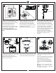
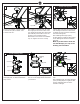
1 2 ON 3 ON Mounting bracket OFF OFF Before you begin installing the fan, Switch power off at Service panel and lock service disconnecting means to prevent power from being switched on accidentally. When the service disconnecting means cannot be locked, securely fasten a warning device, such as a tag, to the service panel. Use AC 120V/60HZ power supply only. 4 Shipping stabilizer Before installing this fan make sure the outlet box is properly installed to the house structure.
9 Safety cable Slot Washer Lock washer Install ball end of downrod into mounting bracket opening. Align (engage) slot on ball with tab on mounting bracket. Warning: Failure to align slot on ball with tab may result in serious injury. Important: If using the angle mount, make sure open end of mounting bracket is installed facing the higher point of the ceiling and make sure the ceiling angle is not steeper than 30º.
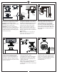
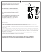
13 14 15 Install LED Light Kit LED light kit Light pan Plate on motor Loosen 2 and remove 1 preassembled screw from the plate on motor. Save screw for later use. 16 Install blanking plate Attach light pan onto the plate on motor, Place light pan over the lead wires from fan, aligning the keyhole slots on the light plate with the preassembled screws on the plate. Twist clockwise till lock. Reinstall the screw remove in installation step 13. Tighten all screws securely.
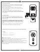
Remote Controller Operation Remove the battery cover from the remote control transmitter and install battery. Replace the cover. This remote uses 12V battery, Duracell MN21 / Evereday A23 / GP 23A all 12V. Note: If not using for long periods of time, remove battery to prevent damage to remote transmitter, and store the remote transmitter away from excess heat or humidity Set/change the dip switch position on the transmitter to desired code setting.
Install Transmitter wall mount cradle with 2 screws provided. Move the trim plate out from wall mount cradle and install the wall mount cradle with 2 screws provided. Replace the trim plate. Trim plate The receiver provides the following protective functions Lock protection- The DC motor has a build-in safety feature against blade obstruction during operation. If something obstructs the fan blades the motor will stop operation after 30 seconds of interruption. Please remove obstacles and reset.
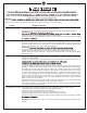
Trouble Shooting or wiring. In some cases, these installation errors may be mistaken for defects. If you experience any faults, installation, please call our Customer Service Center at the number printed on your parts list insert sheet. Warning means to prevent power from being switched on accidentally. When the service disconnecting means cannot be locked, securely fasten a prominent warning device, such as a tag, to the service panel. Trouble 1. If fan does not start: Suggested Remedy 1.
Nov.