
Installation Guide


4
© 2013 Monte Carlo Fan Company
9/25/2013
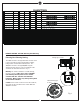
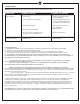
Warning: Before proceeding, be sure to shut off electricity at
main switch or circuit breaker in order to avoid electrical shock.
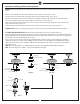
Make wire connections as shown in wiring diagram using wire
connectors provided.
Connect WHITE wire from motor assembly to
WHITE wire from remote control receiver marked TO MOTOR N,
BLUE wire from motor assembly to BLUE wire from remote
control receiver marked FOR LIGHT. Connect BLACK wire from
motor assembly to RED (or BLACK) wire from remote control
receiver marked TO MOTOR L. Connect BLACK (Live) wire from
house to BLACK wire from remote control receiver marked AC IN
L. Connect WHITE (Neutral) wire from house to WHITE wire from
remote control receiver marked AC IN N. Connect GROUND LEAD
(Green ) from fan to GROUND LEAD from house. (Fig. 2)
Note: If the fan includes up light, connect ORANGE wire from fan
to ORANGE wire from remote control receiver marked FOR UP
LIGHT if the remote controller includes up light function.
Note: Make sure there is no bare wire is visible at wire
connectors.
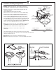
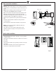
For downrod mount fans, lay the receiver in the canopy as shown
in Fig. 3. For flush mount fans, attach the receiver to mounting plate with wrap
supplied as shown in Fig. 3-1.
Note: Mounting mean of fan may be different than shown.
Note: Electrical rating for fan motor is 1 A max and 300W max for light.
Installation and Wiring (Canopy Mount)
Fig. 2
BLACK/LIVE
(AC IN L)
WHITE/NEUTRAL
(AC IN N)
RED (or BLACK)
(TO MOTOR L)
BLUE
(FOR LIGHT)
WHITE
(TO MOTOR N)
GROUND LEAD WIRE
FROM FAN
GROUND LEAD WIRE
FROM HOUSE
WALL SWITCH
Fig. 3 Fig. 3-1
CEILING
JUNCTION BOX
MOUNTING PLATE
RECEIVER
ANTENNA
BLACK
AC POWER
SUPPLY