Controls. Assembly. Operation. Adjustments. SafeHow Operation To UseY our Practices. Tiller ...3 ...4 ...8 Maintenance. Off-Season Lubrication ...9 Illustrated ...9 ..10 Parts PartsList Storage Parts ... Information. Instructions given with this symbol sonal safety. Be sure to follow them. . 11 11 14 16,18,20,21,22 .17,18,19,20,21,22 BackCover are for per.
18. 6. 22. 13. , ~ WARNING ~ ' To reduce the potential for any injury, comply with the following the instructions may result in personal injury. 1. It is suggested that this manual be read in its entirety before attempting to assemble or operate this unit. Keep this manual in a safe place for future reference and for ordering replacement parts. 14. Do not walk in front engine is running. 3. Read this Owner's Manual carefully.
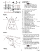
o-J1 c ,~;;'; ~~ ASSEMBLY E-i :jlllR-ir H-@ @ @ I~ @S--@JN-@@~~ NOTE This unit is shipped WITHOUT GASOLINE or OIL. After assembly, see separate engine manual for proper fuel and engine oil recommenda-tions. ., @ @ @ T- e o-@ ~ @ ~ L, ~Contents U--@ v---~ p(:!;)(~~ A ~ Q-~@@@ FIGURE 1.
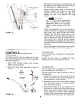
~ 2. 11 ~ Ball Knob (C) Hex Bolt I (A) Flat Washer -(8) Insert clevis pin (0) through the tine shield and depth bar assemblies. Secure with hairpin~cotter (E). See figure 4. e~ #) Hairpin Cotter' (E) , Depth --. 3. Insert hex bolt (A) into the upper hole of the depth bar assembly. Place flat washer (8) onto the hex bolt and thread ball knob (C) onto the hex bolt. See figure 4. Tighten securely. Bar Assembly Shield Clevis Pin (0) ~ ~ Assembly FIGURE 4.
IAI 3. 1. Mount the handle panel (AC) to the handles. Secure with carriage bolts (M), lock washers -(N) and hex nuts (0). See figure 7. NOTE To align the holes in the handle panel and the handle, it may be necessary to loosen the cable brackets which are mounted to the back of the handles tapping screws. THROTTLE CONTROL Assemble the throttle as follows. with self- INSTAllATION control to the handle panel 1. Hold the throttle control assembly beneath the handle panel.
J ~ 2. Hook the "Z" end of tine clutch hole in tine clutch lever. cable into the 3. With the clutch lever released (in the "up" position), adjust the bottom nut at the cable bracket so there is only a slight amount of slack in the control wire. Tighten the upper nut against the bracket. Squeeze the clutch lever against the handle. The control wire ~should now be straight. See figure 10. NOTE Do not overtighten control wire. Too much tension may cause it to break. FIGURE 10.
~~ 6. Secure drive clutch lever to weld bolt with rubber washer (T), flat washer (U) and hex lock nut.,(V). See figure 13. Tighten hex nut. 7. Place the drive clutch lever in the position. Adjust the cables at bracket so that the cables are tighten the hex nuts against neutral (N) the cable tight, then the cable bracket. IMPORTANT Service engine with oil and gasoline before checking the drive clutch adjustment. Refer to the separate engine manual packed with your tiller. 8.
3. Move choke NOTE Engine is shipped without A warm oil. lever to "CHOKE" position. engine require may not choking. 4. Stand at side of tiller. Grasp the starter handle and pullout rapidly. Return it slowly to the engine. Repeat as necessary. BEFORE STARTING 1. Before operating tiller for the first time or if tines have been removed and reassembled for any reason, check to be certain the tines are assembled correctly. The sharp edge of the tines must enter the soil first as shown in figure 15.
Do not push down on the handles so that the wheels are lifted off the ground while the tine clutch is engaged, or the tiller could move backward and cause personal injury. For best results, it is recommended the garden be tilled twice (lengthwise, then widthwise) to pulverize the soil. FIGURE 17. 2. When breaking up sod and for shallow cultivation, use the setting which gives 1V2" of tilling depth (second hole from the top). Place the side shields in their lowest position.
CARBURETOR ADJUSTMENT If any adjustments are made to theengine while the engine is running,(e.g. carburetor), disengage all clutches and tines. Keep clear of all moving parts. Be careful of heated surfaces and muffler. Never make unnecessary adjustments. The factory settings are correct for most applications. If adjustments are needed, refer to the separate engine manual packed with your tiller. 19.
If belt replacement is required, order belt or belts After the first two hours of operating a newengine, by part number from your nearest authorized dealer. drain the oil from the crankcase while the Part No. 754-0195 Tine Belt (1/2" X 54" Long) engine is still hot and refill the crankcase with new oil; thereafter change the oil after every 25 Part No. 754-0190 Reverse Drive Belt (V2" x 39" hours of operation. Long) ENGINE -I Part No.
) ~ tr' -~ ~ 4. C. 13 Wheel Chain Case Pulley / 1-1 < ...~ If, ~ "J/- '~ -~ ~ '-~~,"'~ --'.'- Reverse Drive ~': '",. Wheel Chain Case Pulley .~ve Small I Pulle L J rSOl~1 '" -;') 6) {2)\~~ \~ ~L I) ~J; -'"--:::c:;: ~ " -\- Forward I Two-Step Engine Engine Pulley Pulley FIGURE 25. FIGURE 23. To remove follows. Forward Belt the forward drive belt, proceed as A. Loosen (do not remove) the hex nut at the top of the wire belt keeper. B.
2. DO NOT DRAIN FUEL WHILESMOKING, OR IF NEAR AN OPENFIRE. Drain all the oil from the crankcase (this should be done after the engine has been operated and is still warm) and refill the crankcase with clean new oil as instructed in the engine manual. 3. Protect the inside of the engine for storage as instructed in the separate engine manual packed with your unit. FIGURE 27. 4. Clean the exterior of engine and the entire tiller thoroughly. 5. Wipe tines with oiled rag to prevent rust.
SYMPTOM Engine fails to start Hard starting or loss of power POSSIBLE CAUSE(S) 1. Check fuel tank for gas.2. Spark plug lead wire disconnected.3. Faulty spark plug. 1. Fill tank if empty. 2. Connect lead wire. 1. Spark plug wire loose. 1. Connect and tighten spark plug wire.2. Clean air cleaner as described in engine manual. 2. Dirty air cleaner. overheats 1. Carburetor not adjusted .properly. 2. Air flow restricted. oil revel low. Controls do not engage SOLUTION Belts worn and/orstretched.
r Wire Assembled in Upper Hole on Model TMO-39083A Wire Assembled in Lower Hole on Model TMO.39084A , 2 \ / --71 ~, \\ 78/ '6 94 A -, (\=:J~~3 ~ 69 I ,68 77 '"'" '"/' / /' / 7375 Q \ 72'1!!!1J 86 1 \I. '.- Ii'. 62 61 \ ~ 23, / \ " ' 2 \! \ (- -\1 I ;.- 60-;1' "'11/ 17" , KJ I / 18 / J.9 \ \, ~2 21 / 22 e 18\ sh -'~ / I J / ~ "I ~ / /) -:;'/ (, ~I 36" 0 I47 .17 36 " ~ -' y51 '" " ,:~ / 45 ---52 ""'53 ~\ ~ \ ~" :/1f "," ,,' ~o .
REAR TINE TILLERS PARTS REF. PART LIST FOR MODELS --- COLOR DESCRIPTION NO. NO. CODE 1 710-0299 Hex Bolt 1/4-28 x 1.0" Lg.* 2 720-0180 Grip 3 747-0517 Clutch Lever 712-0117 5 710-0458 7 784-0031 4 9 15093 10 710-0607 11 12 712-0256 736-011913 746-0535 14 15 16 17 18 19 20 21 22 23 24 712-0267 736-0119 784-0133 749-0643 712-0798 736-0169 736-0105 710-0253 714-0507 725-0157 747-0432 Hex Cent. L-Nut 1/4-28 Thd. Carr. Bolt 5/16-18 x 1.75"* Clutch Grip Ass'y.-L.H. Clutch Cable Bracket Hex Wash.
REAR TINE TILLERS PARTS LIST FOR MODELS TMO.39083A I PART COLOR NO. CODE750-0219 DESCRIPTION REF. NO. 2 3 4 5 7 8 9 10 11 13 14 15 16 17 .375" 1.0. x .500" 0.0. x 2.00" Lg. 746-053515093710-0118 Clutch Control Cable (Tines) Clutch Cable Bracket Hex Bolt 5/16-18 x .75" Lg.* 732-0387 Extension Spring .50" 0.0. x 2.50" Lg. 712-0266 Hex Cent. L-Nut 3/8-16 Thd. 712-0107 Hex Cent. L-Nut 1/4" Thd. 732-0445 Extension Spring .50" 0.0. x 1.55" Lg. 15093 Clutch Cable Bracket 710-0118 Hex Bolt 5/16-18 x .
TMO-39084A REAR TINE TILLERS PARTS LIST FOR MODELS TMO.39083A AN D TMO. REF. PART COLOR NO. 43 44 45 46 47 48 49 NO. CODE 736-0176 736-0329 710-0412 712-0116 710-0412 736-0329 736-0176 DESCRIPTION OR FI-Wash. L-Wash. Hex Bolt Hex Ins. Hex Bolt L-Wash. FI-Wash. 1/4" 1.0. X .93" 0.0. 1/4" 1.0.* 1/4-28 x .75" Lg. L-Nut 3/8-24 Thd. 1/4-28 x .75" Lg. 1/4" 1.0.* 1/4" 1.0. x .93" 50 756-0389 FI-Pulley w/Flanges 51 756-0405 FI-ldler 0.0. 0.0.
~~ , '",~ '" ., ,.2 3-? ~~,~ ,/,- i '~I. .\ \\ , -; Lv .'- ",>J~ ~'--'. !Jf"'" '. 36 ". , ~"'2:--~., f{. , ~~~[ ~..Jt~~ .\ \( ~~~ \ I 23 2' 28 ~ 2' ~v1 '9 ~ I 784-0106 3 784-0104 Tines 784-0105 4 710-0189 5 710-0118 6 14973 7 736-0119 8 ~712-0267 91011 710-0830 14975 736-0119 12 723-0340 13 712-0267 14 710-0786 15 736-0326 16 736-0119 17 712-0267 18 712-0267 19 736-0119 2021736-0921 22 23 24 ~ 712-0206 750-0579 1 736-0169 712-0241 O.D. .Wash. 5/16" I.D.
2829I_V \ t/ 2 TILLER I NO. PART NO. I COLOR CODE 14962 2 ~748-0154 3 4 1 784-0136 713-0325 5 713-0316 6 750-0351 7 741-0228 8 9 710-0369 712-0116 10 736-016911 736-0219 12 '113-0330 13 113-0326 14 1784-0126 784-0125 15 16 1 741-0227 736-0265 17 750-0354 ,..10 !REF. 1 19 FI-Wash. CHAIN CASE (WHEELS)fARTS LIST FOR MO~iMO.39083~D DESCRIPTION I NEW ! REF. PART NO. Chain Case Half Ass'y.- , NO. CODE I 18 1736-0265 R.H. Bearing 5/8" 1.0. x .813" 0.0. x 1.31" Lg. Input Shaft Ass'y.
Heavy Duty Rear Tine Garden Tiller Attachments Available for All-Season Use 31-0110 31-0144 31-0145 31-0178 8" Furrower Opener "V".Bar Cultivating Kit (Must be used with 31-0178 adapter) Kit Includes: "V"-Bar Frame, 4-Point Cultivating Tines, Hiller/Furrower, Depth Gauge Wheels (Pair). Depth Stake Cultivating Kit (Must be used with 31-0178 adapter) Kit Includes: 8" Furrower Opener, 15" Sweep Cultivator, 32" Leveling Rake, Extra Depth Stake.
TYPE HOW TO OBTAIN REPLACEMENT PARTS AND SERVICE The merchandise you have purchased from us has been carefully engineered and manufactured under Wards rigid quality standards and should give you satisfactory and dependable operation. However, like all mechanical merchan-dise, It may occasionally require adjustment, replacement parts or maintenance.