
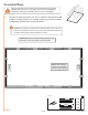
Use and Care Manual
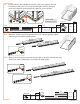

QTYConnector
B-3
S-2C
S-7
2
4
2
56”
QTY
Prole
F-7 1
Panel QTY
W-1 1
24” x 57”
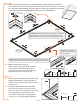
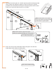
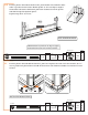
3.1e
Remove plastic film and fit another W-1 panel and fit into channel in base
and F-1 profile. Position left F-8 back profile so the cut edge is angled
toward the left when installed. Fit panel into channel in left F-8 profile
and slide F-8 profile against spacer.
Repeat step 3.1C to secure.
WWW.RSIWW.COM
17 of 43
QTY
Prole
F-8 1
72”
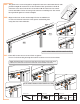
QTYConnector
B-3
S-2C
S-7
1
2
1
Panels QTY
W-1 1
24” x 57”
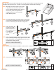
NOTE: VIEW FROM INSIDE.
NOTE: VIEW FROM OUTSIDE.
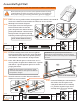
3.2
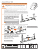
Remove plastic film and add the last W-1 panel to complete the side. From the outside, fit F-7
corner profile into place and use two B-3 connectors with T-bolt assemblies as shown to secure
to base.
NOTE: Position F-8 profile so cut edge is angled
down towards nearest corner when installed.
F-7
B-3
B-3
spacer tool
W-1
F-8
F-1