
Use and Care Manual

WWW.RSIWW.COM
23 of 43
NOTE: VIEWS FROM INSIDE.
NOTE: VIEWS FROM INSIDE.
NOTE: VIEW FROM INSIDE.
NOTE: Panels will not fit completely to end of channels.
There will be some space to allow for temperature changes.
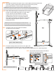
IMPORTANT: The panels expand and contract depending on the temperature.
To ensure proper placement, use the 23 1/8 inch spacer included with the tools.
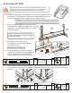
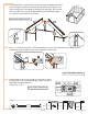
Working from inside front right corner, remove plastic film from both sides
of one W-1 panel. Fit panel into channel in base and corner profile,
placing side marked “ UV Resistant” facing outside.
Place 23 1/8 inch spacer on base next to F-7 corner
profile. Position right F-8 profile so single T-bolt
is next to base on inside and the cut edge
angled down toward the nearest corner when
installed. B-2 connector is pointing towards
door opening. Fit panel into channel in F-8 profile
and slide F-8 profile against spacer to ensure
proper placement.
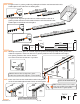
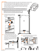
Continue working from inside left corner, place F-6
profile with mitered end next to corner and angled edge
facing up onto corner W-1 panel. F-6 profile fits snugly between F-7 and F-8 profiles.
5.2A
5.2B
5.2c
5.2D
5.2e
W-1
F-7
spacer tool
F-8
B-2
W-1
F-7
F-8
G-1
F-6
Connector
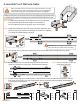
QTY
B-2 1
S-2C 3
B-3
S-2C 2
1
Connector
QTY
W-1 1
Panel
QTY
24” x 57”
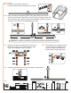
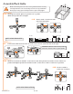
Use B-3 connector with T-bolt assemblies
as shown to secure to base.
B-3
F-8
B-2
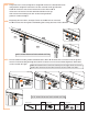
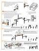
Secure B-2 with two T-bolt assemblies
and one S-2C cap as shown.