Monticello Made in the USA 8’ x 20’ Greenhouse Assembly Instructions 041315V WA RRAN TY Customer Service: (877) 373-3078 Email: customerservice@rsiww.
Thank you for choosing the Monticello Greenhouse Program Thank You for your Purchase We want to thank you for your purchase of the Monticello Greenhouse. We appreciate your support of our American Made Greenhouses. The Monticello is designed for the average homeowner; no special degrees are needed. The time to assemble depends on the weather, skills, options, and number of helpers you have in the process.
MONTICELLO Limited Warranty/ Liability Snow Load & Wind Load Warranty & Liability The Monticello Greenhouse described in this manual is designed for and limited to Riverstone Industries standard wind and snow load which is based on a continuously heated greenhouse. Standard loads are: Wind Load = 113 MPH/ 1 second gust (52m/sec); 65 mph continuous winds, Snow load of 24 lbs. sq ft.
Introduction Thank you for purchasing the Mojave Edition MonticelloTM Greenhouse. The Monticello line is proudly made in the USA by a leading commercial greenhouse maker using the same professional grade materials and design. The frame is constructed with the highest quality extruded aluminum with lead free powder-coated paint. The panels are professional grade 8mm twin wall polycarbonate selected for their insulation and durability.
Safety Advice Table of Contents • The greenhouse must be positioned and fixed on a flat level surface. • Dispose of all plastic bags safely. Keep them out of the reach of small children. • Keep children and pets away from the assembly area until the work is completed. • Always wear work shoes, gloves and safety goggles when working. • Some of the parts have sharp edges and burs. Use extreme caution when handling. • Do not lean against or push the greenhouse during assembly.
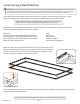
Constructing a Wood Platform IMPORTANT: It is very important to begin with a level surface. Check your foundation to ensure it is level at every point. If you are not building on a wood deck, we recommend constructing a wood platform so you can properly secure the greenhouse. You must assure your foundation is square and level before beginning assembly. After choosing a location, proper preparation of the site is essential. The site must be level.
List of Parts WARNING: Profiles with cut edges and/or drilled holes are sharp. Use extreme caution when handling. The greenhouse is shipped in multiple cartons. These cartons are heavy. Use care when lifting them. Some parts have sharp edges. Use extreme caution when handling. Wear proper safety gear including work shoes, gloves and safety goggles. Keep children and pets away until assembly is complete. Finish assembling the roof in one session.
List of Parts (continued) Door Profiles QTY 24” WARNING: Use extreme caution when handling panels with cut edges. The corners are sharp.
Hardware List of Parts (continued) Door Profiles QTY QTY S-1 16 Step 9 S-2C 415 D-4 20’ Step 10 S-2A S-2B S-2C S-2D 2 2 2 2 Steps 1,2,3,4 5,6,7,8,10,11,12 Step 5 Step 5 Step 5 Step 5 D-6 2 Step 10 S-4 95 Steps 11 S-5A S-5B S-5D 4 4 4 Step 7 Step 8,12 Step 8,12 S-6 8 Step 9 S-7 415 Steps 1,2,3,4 5,6,7,8,10,11 S-8A S-2A 8 8 Step 5 Step 5 S-9 38 Step 10 S-10 4 Step 10 D-7 1 Step 10 D-8 4 Step 5 D-9 8 Step 10 Included Tools D-10 2 Step 10 QTY S-10 1 Steps 1,2
Using T-Bolts IMPORTANT: This greenhouse is assembled using a unique fastening system. The parts are attached to each other using connectors fastened with a rectangular headed bolt referred to as a “T-bolt” and secured with a “2-SC cap”. In this manual you will prepare only the profiles required for each section. This includes installing T-bolts in the locations needed for the entire assembly. The T-bolts with connectors and S-2C bolts secure the profiles in place.
Assemble Base Make certain the pieces are in the correct positions before securing. Carefully follow the order of assembly to ensure an easy installation. Wear proper safety gear including work shoes, gloves and goggles. 1.1 The base is made up of four P-1A, four P-1B, four P-2A and four P-2B profiles. Arrange profiles in a rectangle as shown. Position P-2A and P-2B profiles at back sides of the greenhouse. WARNING: Use extreme caution when handling profiles P-1A, P-1B, P-2A and P-2B.
1.2 Install T-bolts into inside and outside bolt tracks as shown below. Some of the T-bolts are secured in this step. Most are secured in later steps. Pay careful attention to ensure you have the correct number of T-bolts in the correct bolt track in each profile. The profiles have different amounts of T-bolts on the inside and outside bolt tracks. BACK IMPORTANT: Position P-2A and P-2B profiles at back of greenhouse.
1.3A Make certain side profiles are straight and flush. Adjust position of T-bolts in inner bolt track at front of profile to fit holes in B-5 connector. Center connector over seam for maximum hold. Secure using four S-2C caps. Repeat on outer bolt track to install eleven remaining B-5 connectors at back and sides. B-8 B-5 B-5 B-8 B-5 B-5 B-5 BACK IMPORTANT: One B-5 connector is installed on inside front. Remaining B-5 connectors are installed on outside back and sides.
Assemble Right Wall CHECK YOUR WEATHER FORECAST. DO NOT CONTINUE ASSEMBLY DURING WINDS. Make certain the pieces are in the correct positions before securing. Carefully follow the order of assembly to ensure an easy installation. Wear proper safety gear including work shoes, gloves and goggles. 2.1A Place F-7 corner profile on base, fitting panel into channel. Use two B-3 connectors with T-bolt assemblies as shown to secure to base. 2.1B Working from outside, begin at front right corner.
2.3 Remove plastic film and add the last W-1 panel to complete the side. From the outside, fit F-7 corner profile into place and use two B-3 connectors with T-bolt assemblies as shown to secure to base. F-7 B-3 NOTE: VIEW FROM OUTSIDE. B-3 Profile QTY 56” F-7 Panel Connectors QTY 1 24” x 57” W-1 1 QTY B-3 2 S-2C 4 S-7 2 2.4A Slide four T-bolts into bottom bolt track of G-1 gutter profiles. Hand tighten each end T-bolt to hold in place. G-1 G-1 G-1 G-1 2.
2.5A Working from inside, place G-1 and G-2 gutter profiles, fitting top edge of W-1 panels into channels of gutters. Place one short G-1 gutter profile at each end and the four longer G-2 gutter profiles in the center. Seams are centered to bolt tracks in F-1 profiles. G-2 W-1 F-1 NOTE: In some cases a ¼” x ¼” notch in top corner of W-1 panel will provide a better fit for G-1 gutter profile.
2.6A The gutters are secured together using B-5 connectors and attached to side profiles using B-3 connectors on the outside of the greenhouse. The B-3 connector uses the T-bolt in the center hole of B-5 connectors at seams. Loosen and slide T-bolts to line up with connectors making sure the seams line up and the gutters remain straight. 2.6B Begin at the five seams and arrange T-bolts so middle bolt is centered. Fit B-5 connector onto gutter and hold in place using the two S-2C end bolts.
Assemble Back Wall CHECK YOUR WEATHER FORECAST. DO NOT CONTINUE ASSEMBLY DURING WINDS. Make certain the pieces are in the correct positions before securing. Carefully follow the order of assembly to ensure an easy installation. Wear proper safety gear including work shoes, gloves and goggles. 3.1a Working from inside, remove plastic film from both sides of one W-1 panel. Fit panel into channel in base and corner profile, placing side marked “ UV Resistant” facing outside.
3.1e Remove plastic film and fit another W-1 panel and fit into channel in base and F-1 profile. Position left F-8 back profile so the cut edge is angled toward the left when installed. Fit panel into channel in left F-8 profile and slide F-8 profile against spacer. Repeat step 3.1C to secure. F-1 W-1 F-8 spacer tool NOTE: VIEW FROM INSIDE. NOTE: Position F-8 profile so cut edge is angled down towards nearest corner when installed. Connector QTY Profile 72” F-8 Panels 1 24” x 57” 3.
The two sets of F-6 and F-10 profiles fit on top of W-1 panels. Line up bottom bolt channels with top edge of F-1 and F-7 vertical profiles. Profiles will fit snugly. 3.3A Working from inside right corner, place F-6 profile with mitered end next to corner and angled edge facing up onto corner W-1 panel. F-6 profile fits snugly between F-7 corner profile and F-8 back profile. F-6 G-1 F-7 W-1 F-8 F-6 3.3B Continue along back wall. Place first F-10 profile on next W-1 panel.
Assemble Left Wall Make certain the pieces are in the correct positions before securing. Carefully follow the order of assembly to ensure an easy installation. Wear proper safety gear including work shoes, gloves and goggles. 4.1a Continue working from inside back left corner. Remove plastic film from both sides of one W-1 panel. Fit panel into channel in base and corner profile, placing side marked “ UV Resistant” facing outside. IMPORTANT: The panels expand and contract depending on the temperature.
4.3A Prepare two G-1 gutter profiles by sliding four T-bolts into bottom bolt track. Hand tighten each end T-bolt to hold in place. G-1 G-1 4.3B Prepare three G-2 gutter profile with six T-bolts and the other G-2 gutter profile with five T-bolts. Slide T-bolts into bottom bolt track. Hand tighten end T-bolt to hold in place. G-2 G-2 G-2 G-2 Profile QTY 25½” S-7 48½” 31 G-1 2 G-2 4 4.
4.5A The gutters are secured together using B-5 connectors and attached to side profiles using B-3 connectors on the outside of the greenhouse. The B-3 connector uses the T-bolt in the center hole of B-5 connectors at seams. Loosen and slide T-bolts to line up with connectors making sure the seams line up and the gutters remain straight. 4.5B Beginning at the seams, arrange T-bolts so middle bolt is centered. Fit B-5 connector onto gutter and hold in place using the two S-2C end bolts.
Assemble Front Wall and Gable Make certain the pieces are in the correct positions before securing. Carefully follow the order of assembly to ensure an easy installation. Wear proper safety gear including work shoes, gloves and goggles. NOTE: The door frame is 69¼” from the base. To avoid adjusting the placement after assembly, prepare door frame using the exact measurements listed in these steps. 5.1A Prepare four D-8 hinges. Fit S-8 bolts in holes in D-8 hinge. Line up with S-2A nuts under hinge.
5.2A Working from inside front right corner, remove plastic film from both sides of one W-1 panel. Fit panel into channel in base and corner profile, placing side marked “ UV Resistant” facing outside. IMPORTANT: The panels expand and contract depending on the temperature. To ensure proper placement, use the 23 1/8 inch spacer included with the tools. 5.2B Place 23 1/8 inch spacer on base next to F-7 corner profile.
5.3A Working from inside front right corner, place 23 1/8 inch spacer on base next to F-7 corner profile. Position left F-8 profile so single set screw is next to base on inside and the cut edge angled down toward the nearest corner when installed. B-2 connector is pointing towards door opening. Fit panel into channel in F-8 profile and slide F-8 profile against spacer to ensure proper placement. IMPORTANT: The panels expand and contract depending on the temperature.
5.4A Prepare one F-5 profile. Slide four T-bolts into bolt tracks and position as shown. F-5 5.4B Place one end of F-4 profile against F-5 profile on flat level surface. Center F-4 profile to F-5 profile. Insert a T-bolt assembly into the top slot of the B-2, place the B-2 in position and adjust T-bolts to fit B-2 connector. Secure with two additional S-2C caps.
5.5A Working from inside, remove plastic film from both sides of two W-3 panels. Fit each panel into channels in profiles, placing side marked “ UV Resistant” W-3 facing outside. W-3 WARNING: The corners of W-3 panels are sharp. Use extreme caution when handling. 5.5C Secure with two bolts. Ensure height to base is 68¾”. 5.5B Continue working from inside. Position door frame so barrel latch is on outside. Loosen set screws on ends of F-5 profile and adjust position to fit F-5 holes in B-2 connector.
5.8A From outside fit F-7 profiles into each side of front. Begin with either side. Arrange F-7 profile so channel lines up with tops of panels. The side of the profile rests against cut angle of F-8 profile. The top end F-4 touches edge of F-4 center profile and bottom end touches top of G-1 gutter. Position both F-7 profiles. NOTE: VIEW FROM OUTSIDE. F-7 F-7 F-4 G-1 F-8 F-8 F-8 G-1 F-4 5.8B Use C-1 connector with three T-bolt assemblies to secure each outside corner.
Assemble Back Gable Make certain the pieces are in the correct positions before securing. Carefully follow the order of assembly to ensure an easy installation. Wear proper safety gear including work shoes, gloves and goggles. 6.1A Working from inside, place F-2 profile on F-1 profile. Make sure profiles are straight. 6.1b Secure to B-1 connector with one T-bolt assembly. F-2 F-10 F-10 F-11 F-1 Profile QTY 31” NOTE: VIEWS FROM INSIDE.
6.4 Continue working from outside to install panels a shown. Remove plastic film from both sides of two W-3 and two W-4 panels. Fit each panel W-3 into channel in profiles, placing side marked “ UV Resistant” facing outside. W-4 W-4 W-3 NOTE: VIEW FROM OUTSIDE. WARNING: The corners of W-3 and W-4 panels are sharp. Use extreme caution when handling. Panel NOTE: Panels will not fit completely to end of channels. There will be some space to allow for temperature changes.
Assemble Roof Ridge Make certain the pieces are in the correct positions before securing. Carefully follow the order of assembly to ensure an easy installation. Wear proper safety gear including work shoes, gloves and goggles. 7.1A Install B-10 splice with C-curve positioned next to center opening in R-1 profile. Use screwdriver handle to tap until friction dimple holds it in place. 7.1B Install another B-10 splice with C-curve positioned next to center opening in R-1 profile.
7.3A Use two people and a step ladder. Place step ladder inside greenhouse. Hold the roof ridge with the screws FACING UP until it is in position. Have one person inside greenhouse supporting ridge as you slide it into position. Avoid touching top of front and back of greenhouse until each end is flush with ends of front and back profiles. Turn the roof ridge over so bolts face down and rest on top of front and back walls. WARNING: Use two people to install roof ridge. Place ladder in inside of greenhouse.
Assemble Roof Make certain the pieces are in the correct positions before securing. Carefully follow the order of assembly to ensure an easy installation. Wear proper safety gear including work shoes, gloves and goggles. The roof panels are installed in the sections shown below. Use two people and a step ladder to assemble the roof. Place step ladder inside greenhouse. Have one person stand on ladder inside and guide panel into channels in roof ridge and corner profiles.
8.3A Working from back right corner, remove plastic film from both sides of one W-1 panel. With side marked “ UV Resistant” facing outside, fit top end of panel into channel in R-1 roof ridge near corner. Push panel into roof ridge channel until the other end rests on gutter ledge and then slide towards F-7 corner profile. Repeat to install W-1 panel in back left corner. R-1 F-7 W-1 G-1 W-1 F-7 R-1 R-1 F-7 W-1 W-1 F-7 G-1 W-1 G-1 NOTE: VIEWS FROM OUTSIDE. 8.
8.4A Remove plastic film from both sides of one W-1 panel. With side marked “ UV Resistant” facing outside, install the next panel on the right at the back. Push panel into roof ridge channel until the other end rests on gutter ledge and then slide towards F-1 profile at back. Repeat to install W-1 panel on left. W-1 W-1 NOTE: VIEWS FROM OUTSIDE. 8.4b Fit one F-1 profile next to panel. Fit lower end into B-4 connector and secure with one T-bolt assembly as shown.
8.5A Return to back to install section three and remove bungee cord nearest to back. Remove plastic film from both sides of one W-1 panel. With side marked “ UV Resistant” facing outside, install the next panel on the left at the back. Push panel into roof ridge channel until the other end rests on gutter ledge and then slide towards F-1 profile at back. W-1 panels are *NOTE: W-2 installed in step 8.8 8.5B From inside, hold profile in place with one B-4 connector.
8.6A Remove next bungee cord and continue working from back to install section four. Remove plastic film from both sides of one W-1 panel. With side W-1 marked “ UV Resistant” facing outside, install the next panel on the left at the back. Push panel into roof ridge channel until the other end rests on gutter ledge and then slide towards F-1 profile at back. NOTE: VIEW FROM OUTSIDE. 8.6B From inside, hold profile in place with 8.6C one B-4 connector. Secure with two T-bolt assemblies as shown.
8.7A Remove next bungee cord and continue working from back to install section five. Remove plastic film from both sides of one W-1 panel. With side marked “ UV Resistant” facing outside, install the next panel on the right at the back. Push panel into roof ridge channel until the other end rests on gutter ledge and then slide towards F-1 profile at back. W-1 NOTE: VIEW FROM OUTSIDE. 8.7B From inside, hold profile in place with one B-4 connector. Secure with two T-bolt assemblies as shown.
8.8A Continue working from back to install section six. Remove plastic film from both sides of one W-1 panel. With side marked “ UV Resistant” facing outside, install next panel at W-2 slight angle on left. If necessary, loosen the previous B-4 W-2 connector and profile and move them towards the back of the greenhouse W-1 to make more room to fit panel in place. W-2 W-2 NOTE: VIEWS FROM OUTSIDE. W-1 F-1 8.8B Remove plastic film from both sides of one W-2 panel.
8.8 Have one person stand outside the greenhouse to observe the position of the roof ridge while the other person installs the four B-9 braces. Insert T-bolt in the correct position, but if the roof is not completely straight, adjust the brace to raise or lower the roof line. Secure each with two S-2C caps. Brace B-9 QTY B-9 S-2C NOTE: VIEWS FROM INSIDE. 8.9 4 8 The G-4 and G-4E trim plates snap into G-1 and G-2 gutter profiles to hold roof panels in place.
Install Roof Vents Make certain the pieces are in the correct positions before securing. Carefully follow the order of assembly to ensure an easy installation. Wear proper safety gear including work shoes, gloves and goggles. 9.1A Unpack contents of Automatic Window Opener. Screw adjusting knob partially into threaded end of cylinder. Do NOT tighten. adjusting knob cylinder 9.1B 9.1B Fit piston rod connected to arm B into end of cylinder. Turn cylinder so holes next to adjusting knob are visible.
9.2C Screw two S-1 screws through V-2 panel. Line up gripping channel on other side. Continue to screw until secure. Do not over tighten as it may damage the vent. V-2 gripping channel 9.2D Repeat steps 9.2A through 9.2C to prepare three more vents. V-2 S-1 Connector NOTE: VIEWS FROM INSIDE. NOTE: VIEW FROM OUTSIDE. QTY S-1 QTY Gripping Channel 8 4 9.3A From inside, hold Window Opener closed against vent. Slide vent at an angle through opening in roof panels.
Assemble and Install Doors Make certain the pieces are in the correct positions before securing. Carefully follow the order of assembly to ensure an easy installation. Wear proper safety gear including work shoes, gloves and goggles. IMPORTANT: You are assembling a right and left door. Facing the front of the greenhouse from the outside with the doors closed, the left door is on the left side of the greenhouse and the right is on the right side. The left door closes over the right and locks at the top. 10.
10.2A Repeat step 10.1A to prepare another E-2 door profile. D-9 corner connectors are secured in step 10.2B. Slide E-2 profile into E-1 door profiles as shown. E-1 E-2 E-2 D-9 10.2B Position E-4 on top of E-2 profile. Line up holes in E-4 profile with E-2 profile. Secure with five S-9 screws. The final S-9 screw, right below the E-3 profile, is installed in step 10.6B. E-4 S-9 E-4 S-9 E-2 E-4 E-2 10.2C Turn door over and install handle on E-2 profile just secured.
10.4A S-9 F-8 NOTE: VIEWS FROM OUTSIDE. D-9 IMPORTANT: Make sure door is level. When necessary loosen screws holding D-8 hinge to F-8 profile and repostion until it is level. E-2 S-9 10.4B Install left door assembled in step 10.3. Line up holes in D-8 hinges with holes in E-2 door profile. Secure each hinge with two S-9 screws and make sure door is level. Make sure D-7 latch fits into B-3 connector to lock doors. D-7 Connector B-3 10.
Secure to Platform Make certain the pieces are in the correct positions before securing. Carefully follow the order of assembly to ensure an easy installation. Wear proper safety gear including work shoes, gloves and goggles. 11.1 The base has predrilled holes in the inside and outside bolt channels making it easy to secure your greenhouse to a wood platform. Use one S-4 wood screw in each hole in the base. Screw through the wood platform until each screw is flush with base profile.