
Use and Care Manual
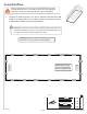


Prole QTY
F-1 11
56”
Panel
QTY
W-1
10
24” x 57”
Panel
QTY
W-1
1
24” x 57”
W-1
W-1
F-7
spacer tool
F-1
Prole QTY
F-7 1
56”
Connectors
QTY
B-3 2
S-2C 4
S-7 2
Connectors
QTY
B-3 11
S-2C 22
S-7 11
WWW.RSIWW.COM
12 of 45
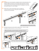
Assemble Right Wall
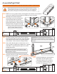
CHECK YOUR WEATHER FORECAST. DO NOT CONTINUE ASSEMBLY DURING WINDS.
Make certain the pieces are in the correct positions before securing.
Carefully follow the order of assembly to ensure an easy installation.
Wear proper safety gear including work shoes, gloves and goggles.
Place F-7 corner profile on base, fitting panel into channel. Use two B-3
connectors with T-bolt assemblies as shown to secure to base.
2.1A
Working from outside, begin at
front right corner. Remove plastic
film from both sides of one W-1
panel. Fit panel into channel in base,
placing side marked “UV Resistant”
facing outside. The panels will help
hold the profiles up during assembly.
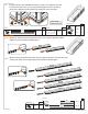
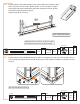
2.1B
Continue working from inside. Remove plastic
film from both sides of one W-1 panel. Fit panel
into channel in base and corner profile, placing
side marked “ UV Resistant” facing outside.
2.2A
Place 23 1/8 inch spacer on base next to F-7
corner profile. Fit panel into channel in F-1 profile
and slide F-1 profile against spacer to ensure
proper placement.
2.2B
Use B-3 connector with T-bolt assemblies as
shown to secure to base.
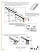
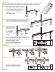
2.2c
Continue building the side wall from
the inside. Use the spacer with
each panel and the ten remaining
F-1 profiles. Repeat steps 2.2A
through 2.2C to secure to base.
2.2D
NOTE: VIEWS FROM OUTSIDE.
NOTE: Panels will not fit completely to end of
channels. There will be some space to allow for
temperature changes.
B-3
F-8
NOTE: VIEW FROM INSIDE.
F-7
B-3
B-3
IMPORTANT: The panels expand and contract
depending on the temperature. To ensure proper
placement, use the 23 1/8 inch spacer included with
the tools.