
Installation guide

Page 4
Part No. XG0509
DFSP Rio Pedestal Stove
Quality Gas Products by Montigo
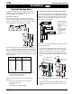
Direct Vent Installation
This section covers the installation of venting and terminations.
Installation Requirements
Rio Stoves are certified for use with Montigo Standard Series (4"
/ 7") venting components and approved Vent Kits (listed below)
Minimum 1" clearance to combustibles required for vent pipes
Use only certified Montigo vent components. (Use of other parts
will void the Montigo warranty, and may impede the operation of
the stove.)
All joints must be secured with a minimum of two screws per joint
Vent terminations must not be recessed in walls or siding
Horizontal runs must be supported by a minimum of two supports
per horizontal run. A minimum of one screw on each side of sup-
port is also required
Flex vent sections may be stretched up to 50% of their total length
(eg. a 24" section may be stretched to 36")
Maximum horizontal run for a flex section with no vertical rise is 3
feet.
Flex vent sections over 3 feet must fall within the limits set by the
venting graph and must have a minimum vertical rise of 3 inches
per foot of flex.
Venting components can be used in any combination of solid/rigid
Solid vent sections may be cut less than half way from the tapered
end
Venting components can be used in any combination of solid/rigid
pipe or flex pipe and in any orientation (Male connectors can face
in any direction)
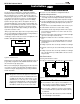
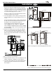
Vent Terminations
Selecting A Termination Location
Choosing your vent termination location will help to determine whether
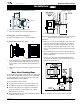
Installing The Gas Line
The gas line must be installed before completing the installation.
Natural Gas requires a minimum inlet gas supply pressure of 5.5"
W.C. & a manifold pressure of 3.5" W.C. Propane Gas requires a
minimum inlet gas supply pressure of 11" W.C. & a manifold pressure
of 10" W.C. Provision must also be made for a 1/8" N.P.T. plugged
tapping and be accessible for test gauge connection immediately
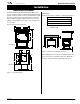
upstream of the gas supply controls to the appliance. The stove is
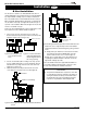
supplied with a flexible gas connector which is factory installed. The
gas valve is located behind the pedestal base, and is accessible from
the back or by removing the control panel cover plate. It should be
attached to the gas line with an approved fitting, as required by the
applicable installation codes.
• Only use gas shut-off valves approved for use by the state, province,
region, or governing body, in which the appliance is being installed, or
as required by the applicable installation codes.
• Flexible gas connectors must not exceed 3 feet in length, unless it is
allowable within applicable installation codes.
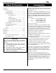
Installation
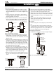
Figure 5. Fireplace locations and vent terminations.
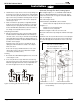
Note: After gas line is connected, each appliance connection,
valve and valve train must be checked while under normal
operating pressure with either a liquid solution, or leak
detection device, to locate any source of leak. Tighten
any areas where bubbling appears or leak is detected until
bubbling stops completely or leak is no longer detected.
DO NOT use a flame of any kind to test for leaks.
During any pressure testing of the gas supply piping that
excedes 1/2
psig (3.5 kPa), the appliance and its individual shutoff valve must be
disconnected from gas supply system.
When pressure testing the gas supply piping system at test pressures
of less than or equal to 1/2 psig (3.5 kPa), the appliance must be
isolated from the gas supply piping system by closing its individual
manual shutoff valve.
Figure 4. Gas line access.
Cautions:
Vent terminations can be very hot. If the termination is less
than 7 feet above a public walkway, it should be fitted with a
certified Montigo Heat Guard. (Part no. MTKOG)
Do not obstruct, or attempt to conceal, the vent termination.
These actions will affect the operation of the fireplace, and may
be hazardous.
In heavy snow areas, take extra care to prevent snow buildup
from obstructing the vent termination.
Direct Vent