
Installation guide

Page 8
Part No. XG0509
DFSP Rio Pedestal Stove
Quality Gas Products by Montigo
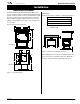
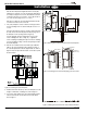
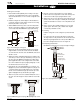
4. Install the first stove pipe onto the conversion box by sliding it over
the flex pipe (refer to Figure 14). Install a spacer spring around the
flex liner. Secure the pipe with at least two ½" hex screws spaced
approx. 3/4" from the joint. Slide the remaining vertical stove pipes
into place, without fastening them. Install a spacer spring inside
each stove pipe section.
5. Cut the horizontal stove pipe (FST11) to length. Slide it and the
90°elbow over the flex and onto the vertical pieces of stove pipe.
Install the last spacer spring inside the horizontal section. Slide
the Decorative Wall Plate (Part # FST07) onto the horizontal sec-
tion, making sure the unpainted side faces the wall.
Completing the Vent Run
6. Slide the stove back into position so the pipe protrudes through
the wall. Pull the flex forward and attach it to the termination (or
other vent sections, if necessary, to extend the vent run) with high
temp sealant. Run a bead of high temp sealant around the stove
pipe and push the termination on. Attach the MTO-3 termination to
the wall as shown on page 5.
Adjust the position of the stove pipes so thethat joints are all
equally spaced. Ensure that there is at least 1 1/2" overlap be
-
tween each section.
Secure each stove pipe joint with at least three ½" hex screws
spaced approx. 3/4" from the joint (so that the brass ring will
cover both the joint and the screws).
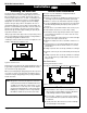
Finishing
7. Now slide the Decorative Wall Plate against the hole, level it, and
secure using four screws.
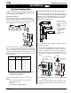
8. Cover each joint in the stove pipes with a brass decorator ring.
The rings should cover the joint as well as the sheet metal screws.
Attach the ring using the black 3/8" screws provided. Make sure
the screw is facing the back of the stove. See Figure 15.
Installation
Direct Vent
FRBV005
Figure 15. Installing the decorative brass rings.
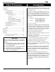
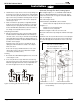
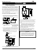
Figure 16. Vertical installation options. Left: straight vertical installa-
tion (no offsets).
B) Vertical (Through-The-Roof ) Venting Option
When venting through the roof, use an FSTK04 Vent Kit. Additional
stove pipe or Montigo Standard Series vent components may be
used to increase the vent run, as long as the run still falls within the
limits set out in Figure 16.
Vertical Vent Requirements:
Vertical terminations (Part # MVTK-1) must be installed:
• minimum 2' above the highest point where the vent passes
through the roof
• minimum 6' from a mechanical air inlet
• minimum 18" from a parapet wall
Maximum vent height is 25 above the stove's flue collar.
(Note: Flame characteristics may change if the maximum vent height
is used.)
A maximum of two offsets
(each offset has two 90° bends) may be
made. The total length of the offset(s) must not be more than 25% of
the vertical vent height, when measured from center to center of the
piping.
Example: Vertical vent height - 20 feet
25% of 20' = 5' max. offset allowed
2 - 2' offsets required = 4' offset
This vent configuration is acceptable.
FSTRO1