
Installation guide


Page 8
H34D Gas Fireplace
Part No. XG0130
Installation
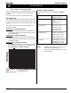
Horizontal Venting
Figure 12. Typical Top Vent installation. The solid sections can be used in
various combinations to obtain the desired vent run. The vent
run must fall within the limits set by the venting graph.
Example 2:
Rigid sections and an elbow used in conjunction with 3 ft. flex section
(MFL-3) will, when extended in a five foot chase, allow for a maximum
horizontal run of twelve and one-half feet from the centre of the fireplace
to outside wall and a minimum of 7'6" when retracted in opposite direction
(see Figure 13 and 14).
"C" flex sections and "D" rigid sections may be used in conjunction with
one another to obtain different possible horizontal length installations.
Figure 13. Extended Installation using a combination of solid and flex
venting. Use the vent graph to determine your allowable
run, then select appropriate components.
Figure 14. Retracted Installation using a combination of solid and flex
venting. Use the vent graph to determine your allowable
run, then select appropriate components.
Figure 15. Horizontal flex installation with no vertical rise.
90° Elbow
MEXT
Section
Termination
Example 1:
For our shortest venting configuration use components A and E (see
Figure 9a).
Figure 11. Typical Top Vent installation. If the 90° elbow is installed
directly on the fireplace, the height to the center of the
termination is 42 1/4".