
Owner`s manual


XG0146 - 042811
Installation
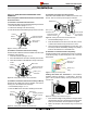
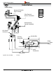
Corner installation.
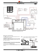
Flex installation. (NG Models Only)
Attach an EEL-45 (45° elbow) directly onto the ue collar. Cut the
MXT-20 to suit, and attach it to the EEL-45. Slide the replace into
position and attach to the termination.
Use an MTO-4 termination and an MFL-1 or MFL-2 (12" or 24"
compressed length) and a frame, if appropriate.Flex may be turned
to obtain desired degree of angle required but must not exceed 45°.
The Kit includes a heat
shield, a MFL-12 (f/f) exible pipe, and a termination with or without
a mounting frame.
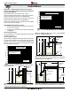
RHS 100
Connection and installation of the vent components should adhere to
the following guidelines:
The following components and associated Montigo part numbers are
available for installation of a Wall Mounted Termination. Use only Montigo
Vent Components. Use of non-Montigo parts will void the warranty and
may impede operation of the replace.
º
º
º
º
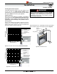
Use any combination of rigid and Flex pipe as required.
Flex sections may be stretched up to 50% of their total length
(e.g. a 24” section maybe stretched to 36”).
Connect all vent sections using a minimum of three sheet metal
screws on the outer pipe ue..
Ensure the pipe ends male to female slide in a minimum of 1
1/2” of overlap.
Ensure all runs are supported with a minimum of 3 supports
per 10’ of venting.
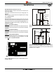
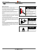
When hanging/ supporting venting, ensure that 1” clearance
is maintained on sides and bottom of vent runs and 2” above
horizontal vent runs to any combustible material.
Ensure when cutting sections of rigid pipe to maintain integrity
of internal supports.
Place the springs, supplied with the pipe kit, between the outer
and inner pipes to keep the pipes separate and avoid any
possible hot spots.
Montigo recommends the use of a ex section for the nal pipe
connected directly to the replace offering greater exibility of
installation and absorption of movement.
When penetrating a combustible ceiling, a ceiling restop must be used.
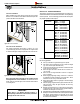
Montigo recommends that all exterior corners and joints be sealed
with exterior caulking however we encourage you to consult
your Building Envelope Engineer or Waterproong Consultant
for further recommendations.
MXT-20
EEL-45
RHS 100