ASSEMBLY & OPERATING INSTRUCTIONS Liquid Propane Gas Grill • Parts • Assembly • Safety Rules • Use and Care • Troubleshooting WARNING: Read this Owner’s manual carefully to ensure your gas grill is properly assembled, installed and maintained. Failure to follow these instructions could result in serious injury and/or property damage. This gas grill is intended for OUTDOOR use only and is not intended to be installed in or on recreational vehicles or boats.
Table of Contents Safety Precautions Warranty …………………………………………. 2 Safety Precautions ...………………………… 2-4 Hardware List ………………………………....... 5 Parts Diagram …………………………………... 6 Parts List ………………………………………… 7 Assembly Instructions …………………….. 8-17 Lighting Instructions ………………………17-19 Cleaning and Maintenance ……………… 20-21 Troubleshooting ……………………………….21 Cooking Instructions ………………………… 22 Cooking Chart ………………………………… 23 Natural Conversion …………………...…..
Safety Precautions • Have your LP gas tank filled by a reputable propane gas dealer and visually inspected and requalified at each filling. • Do not store a spare LP gas tank under or • Never fill the tank beyond 80 percent full . If this information is not followed exactly a fire causing death or serious injury may occur. • Always keep LP gas tanks in an upright position. • Do not store (or) or use gasoline or other flammable vapors and liquids in the vicinity of this gas grill.
WARNING A strong gas smell or hissing sound of gas indicates a serious problem with your gas grill or the LP gas tank. Failure to immediately follow the steps listed below could result in a fire or explosion that could cause serious bodily injury, death, or property damage. • Shut off gas supply to the gas grill. • Turn the control knobs to OFF position. • Put out any flame with a proper fire extinguisher. • Open Grill Lid. • Get away from the LP gas tank. • Do not try to fix the problem yourself.
Contents for Hardware Pack The following table illustrates a breakdown of the hardware pack. It highlights what components are used in the various stages of assembly. A 5/32"x12mm 11 pcs B 1/4"x15mm 13 pcs C 2 pcs D 1/4'' 4 pcs Tools required for assembly Philips Head Screwdriver (not included). Note: The left and right sides of the grill are on your left and right as you face the front of the grill.
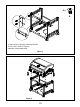
C LOW P SIG GLOBAL Q Model 41847NG Parts Diagram 6
Model 41847NG Parts List seq. appellation NO. qty Material code seq. appellation NO.
Assembly Instructions Insert Part No.47 into the bottom plate. Figure 1 Half screw out the screws in the bottom plate, attach Part No.35 and Part No.40 onto the relevant screw holes and screw tightly.
4x B Install Part No.38 onto the relevant place with four B screws. Figure 3 Half screw out the screws in the bottom and side plates, attach Part No.45 onto the relevant screw holes and screw tightly.
4x A Install Part No.37 onto the relevant place with four A screws shown in Figure 5. Attention: magnet downward.
4x B Screw the grill body and the cart tightly with four B screws. (Figure 7.1) Figure 7.1 Figure 7.2 2x B 2x D 1.Half screw out the three big screws outside the grill body, attach Part No.25 onto the relevant screw holes and screw tightly. 2.Screw Part No.25 tightly with B screw and D spacer inside the grill body. Figure 8.1 Figure 8.
1. Insert the wire of Part No.23. 2. Put Part No.2, Part No.3 onto the Main Lid. Figure 9 2x 1. Insert Part No.30, Part No.32 and Part No.33 as the figure shows. 2. Insert the wire as the figure shows.
1.Half screw out the screw in Part No.27, insert into the hole of Part No.22 and screw tightly. Figure 11 2x B 2x D 1.Half screw out the three big screws on the grill body, attach Part No.69 onto the relevant screw holes and screw tightly. 2.Screw Part No.69 tightly with B screw and D spacer inside the grill body. Figure 12.1 Figure 12.2 13 Figure 12.
1x A Fixed Part No.58 onto the right plate with one A screw. Figure 13.1 Figure 13.2 4x A C C 1. Install Part No. 50 onto Part No.51 with A screws. (Figure 14.1) 2. Put the C part into the relevant hole in the bottom plate. (Figure 14.2) 3. Put Part No.51 into the C part. (Figure 14.2) 4. Attach the doors by pressing the flexible axis upward. Figure 14.1 Figure 14.2 14 Figure 14.
2x A 1. Install Part No.14 onto Part No.16 with two A screws. (Figure15.1) 2. Put Part No.15 into Part No.14. (Figure15.1) 3. Put the grease tray into the grill body. (Figure15.2) Figure 15.1 Figure 15.2 Put Part No. 7, Part No. 8 , Part No. 9 into the relevant place.
1 2 3 Connect Part No.54 to Part No.41. Figure 17 1x B 1.Install Part No. 48 onto the bottom plate. 2.Install Part No. 26 onto the side plate.
Connecting LP Gas Tank to LP Grill 1. Place foot ring of 20 lb. tank into the hole in bottom panel. Make sure the tank valve is in OFF position.(Fig.20). 2. Check the tank valve to ensure it has proper external mating threads to fit the hose and regulator assembly provided. 3. Make sure all burner valves are in OFF position. 4. Inspect the valve connection port and regulator assembly. Look for damage or debris. Remove any debris. Inspect hose for damage. Never use damaged or plugged equipment. 5.
Checking for LP gas leaks Never test for leaks with a flame. Prior to first use, at the beginning of each season, or every time your LP gas tank is changed, you must check for gas leaks. 1. Make a 50/50 (soap/water) mild soap solution. 2. Turn the control knobs to full OFF position; turn gas ON at supply tank. 3. Apply the soap solution with a clean brush to all gas connections. See below. If growing bubbles appear in the solution the connections are not properly sealed.
WARNING Never lean over the grill cooking area while lighting your gas grill. Keep your face and body a safe distance (at least 18 inches) from the cooking grid surface when lighting your grill by match. Manually Lighting Your Grill by Match 1. Take the manual lighting stick 2. Insert a match into the lighting stick. 3. Follow steps 1 through 5 of the Basic Lighting Procedure. 4. Light the match and extend the lighting stick to cooking grid surface. 5.
Cleaning and Maintenance Cleaning Exterior Stainless Steel Surfaces To ensure a proper working unit the following proper care and maintenance is suggested. Cleaning Cooking Grids We suggest you wash your cooking grids in a mild soap and warm water solution. You can use a washcloth or soft brush to clean your cooking grids. Cleaning Heat diffusers Periodically you should wash the heat diffusers in a soap and warm water solution. Use a soft brush to remove stubborn burnt-on cooking residue.
Regardless of which burner cleaning procedure you use, we recommend you also complete the following steps to help prolong burner life. 1. Use a fiber pad or nylon brush to clean the entire outer surface of each burner until free of food residue and dirt. 3. Inspect each burner for damage (cracks or holes) and if such damage is found, order and install a new burner. After installation check to ensure that gas valve orifices are correctly placed inside the ends of the burner tubes.
Cooking Instructions WARNING Do not leave the grill unattended. Your grill will get very hot. Never lean over the cooking area while using your grill. Do not touch cooking surfaces, grill housing. Grill Lid or any other grill parts while the grill is in operation, or until the grill has cooled down after use. Failure to comply with these instructions may result in serious bodily injury.
Grill Cooking Chart FOOD Weight or thickness Temperature Time Special instructions and tips Vegetables NA Medium 8 to 20 minutes Slice or chop vegetables and dot with butter or margarine. Wrap tightly in heavy duty foil. Grill turning occassionally. Potatoes Whole Medium 40 to 60 minutes Wrap individually in heavy duty foil. Cook rotating occassionally. 4 to 15 minutes Pre heat grill for 15-20 minutes then sear steaks on each side for two minutes.
Natural Gas Conversion WARNING! FAILURE TO HEED THESE WARNINGS COULD RESULT IN A FIRE OR EXPLOSION THAT COULD CAUSE SERIOUS BODILY INJURY, DEATH OR PROPERTY DAMAGE. Natural Gas Conversion must be performed by a QUALIFIED GAS TECHNICIAN ONLY. The QUALIFIED GAS TECHNICIAN should ensure compliance of local codes, including but not limited to, requirements and installation of grill regulator. DO NOT ATTEMPT TO CONVERT YOURSELF.
GAS CONVERSIONS 1. Turn off the main gas supply valve. 2. Disconnect LP gas fuel tank (if present). 3. Turn off all burner control valves. 4. Remove the LP gas fuel tank (if present) from the grill cart. 5. Use an adjustable wrench to remove the LP regulator from the manifold. 6.Use an adjustable wrench to install the Natural gas regulator hose to the manifold and secure. Attach the Natural gas regulator to the side panel inside the grill cart with the two screws that are preassembled on the regulator. 7.
Make Gas Connection 1.Pass the NG hose to grill cart through the back panel 2.Connect the brass connector on one end of the 10 ft (3.0m) PVC flexible gas supply hose to the Natural gas pressure regulator AL OB GL AL GLOB PSIG 26 LOW Q C IG PS W LO Q C 3.Connect the quick connector on the other end of the 10 ft. PVC flexible gas supply hose to the rigid natural gas supply pipe. 4.
Change Grill Main Burner Valve Orifices 1. Remove the grates and flame tamers. 2. Push back the Clamp Spring which hold the burner in place,the clamp spring will drop off to grease tray or grill cart 3.Remove the burner from the grill by lifting the burner out 4:Use a 6 mm socket and wrench or 6 mm nut driver to remove the brass orifice from the end of gas valve. 5.Replace with the Natural gas orifice. 6.Reinsert the burner and reattach using the Clamp Spring previously removed.
Change the Side Burner Orifice 1:Remove the LP Side Burner Orifice,and install the NG Side Burner Orifice Adjust High/Low Flame Setting Screw 1:Remove all the control knobs 2:Use a flat-blade screwdriver to turn the high flame setscrew clockwise approximate 90º 3:Check that burner operates at the new high flame setting.
2 1 3 soap 50 % 50 % 4 A 4 B 29
WWW.MONUMENTGRILLS.
WWW.MONUMENTGRILLS.
WWW.MONUMENTGRILLS.